Insulation cover molding die at busbar overlapping part

A technology for forming molds and insulating covers, which is applied in the field of forming molds, can solve the problems of messy busbar chambers, fixed clamping of insulating covers on metal busbars, slipping off of metallic busbars 72 or bolt caps 73, etc., and achieves tightness of metal busbars Effect

Active Publication Date: 2013-05-08
汕头市众业达电器设备有限公司
View PDF3 Cites 0 Cited by
  • Summary
  • Abstract
  • Description
  • Claims
  • Application Information

AI Technical Summary

Problems solved by technology

[0005] But there is following deficiency in above-mentioned existing way: Figure 4 As shown, when the heat-shrinkable sleeve is covered with the solid metal model 9, during the heat-shrinking process of the heat-shrinkable sleeve, since it only relies on the shrinkage performance of the plastic heat-shrinkable sleeve itself to shrink, the adjacent points of the plastic heat-shrinkable sleeve They are involved in the shrinking process, and the heat shrinkage rate of each point can only change gradually. The plastic heat shrinkable sleeve is at the corner of the mold image 3 , Figure 4 Points A, B, C, and D) cannot form a relatively sharp right angle, and the tube wall of the heat-shrinkable sleeve cannot shrink to close to the corner point, but forms an arc-shaped corner at this part, such as Figure 4 , Figure 5 As shown, and the radius R of the arc is very large, which is close to the height of the upper part of the solid metal mold. Therefore, the final plastic insulating cover product made by using the traditional solid metal mold has the following three characteristics: (1). Large width, small groove bottom width, such as Figure 5 As shown, the width m of the notch of the insulating cover 81 is obviously greater than the width n of the groove bottom; (2), the excessive arc radius of the corner of the groove edge 85 and the groove wall 84 is large, such as Figure 5 , Figure 4 As shown; (3), the groove walls 84 on both sides are arc-shaped, and the radius R of the arc is very large, such as Figure 5 shown
Obviously, after the above-mentioned insulating covers 81, 82 are set on the outside of the metal bus bar 72 (or outside the bolt cap 73), although the groove walls 84 on both sides will produce a lateral clamping force on the metal bus bar 72 or the nut 73, the clamping force Not only the insulating cover 81, 82 cannot be fixedly clamped on the metal busbar (or clamped on the nut), but it is very easy to make the insulating cover 81, 82 slip away from the metal busbar 72 or the bolt cap 73 (the slipping direction is as follows: Image 6 indicated by the middle arrow)
[0006] Because the insulating cover made of the existing solid metal model cannot be clamped on the side of the metal bus bar or nut by itself, it is easy to slip off, so it is necessary to punch holes on the edge of the insulating cover, such as figure 2 As shown, and use the cable tie that passes through the small hole 53 to fasten the insulating covers 81, 82 on the overlapping parts of the metal bus bars, as figure 2 As shown, this is cumbersome, and it also makes the metal bus bar look not tight, and makes the bus bar room look messy
[0007] In addition, in the prior art, corresponding to vertical busbars of different width specifications, solid metal molds of different specifications need to be processed separately, which consumes a large amount of metal

Method used


Image

  • Insulation cover molding die at busbar overlapping part
  • Insulation cover molding die at busbar overlapping part
  • Insulation cover molding die at busbar overlapping part

Examples


Embodiment 2

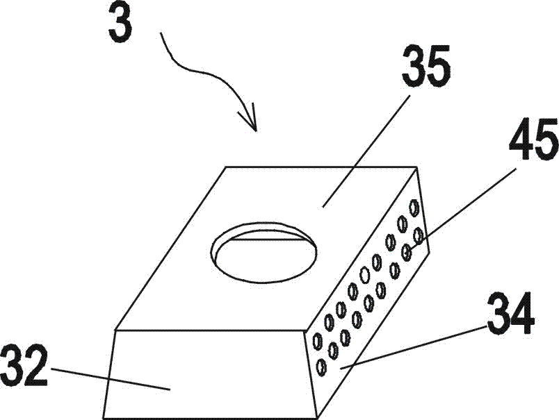
[0059] In the second embodiment, there are three hollow metal boxes welded together, the structure of the upper metal box 1, the middle metal box 2, and the lower metal box 3 is exactly the same as that of the first embodiment, except that In addition, the second embodiment is also equipped with an upper widening die sleeve 5 and a lower widening die sleeve 6, such as Figure 18 shown. The upper widening mold cover 5 is provided with five side walls, namely the top wall 55, the bottom wall 56, the right wall 54, the front wall 51, and the rear wall 52 of the upper widening mold cover 5, and the lower widening mold cover 6 is also provided with Five side walls, i.e. the top wall 65, the bottom wall 66, the right wall 64, the front wall 61, and the rear wall 62 of the lower widening die sleeve 6.

[0060] Figure 21 , Figure 23 As shown, the left side of the upper widening die cover 5 is hollowed out, and the left side of the lower widening die cover 6 is hollowed out; Fig...


PUM

PropertyMeasurementUnit
diameteraaaaaaaaaa

Abstract

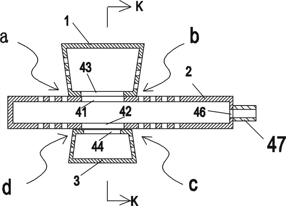
The invention discloses an insulation cover molding die at the busbar overlapping part. The insulation cover molding die at the busbar overlapping part comprises an upper metal box body, a middle metal box body and a lower metal box body which are welded together, wherein the horizontal width of the middle metal box body is greater than the horizontal widths of the upper metal box body and the lower metal box body; the longitudinal length of the intermediate metal box body is equal to the longitudinal lengths of the upper metal box body and the lower metal box body; a general air absorption hole is formed on the right wall of the intermediate metal box body, and is connected with a metal air pipe; a plurality of small air absorption holes with the diameters of 0.5-1mm are formed on the left wall and the right wall of the upper metal box body; and a plurality of small air absorption holes with diameters of 0.5-1mm are formed on the left wall and the right wall of the lower metal box body. According to the invention, the manufactured plastic insulation cover can be clamped automatically and attached to a metal busbar.

Description

[0001] technical field [0002] The invention belongs to the technical field of power distribution equipment, and in particular relates to a molding die required for making an insulating cover at the overlapping part of a busbar. Background technique [0003] In recent years, most users of power distribution cabinets require that all exposed metal bus bars in the cabinet must be equipped with insulating heat-shrinkable sleeves. figure 1 As shown, it is relatively easy to put the heat-shrinkable sleeve on the metal busbar 70 of the straight section. It is enough to directly put the plastic heat-shrinkable tube 8 on the surface of the busbar. The penetration method (insertion method) is as follows: figure 1 indicated by the middle arrow. But at the overlapping position where the horizontal bus 71 and the vertical bus 72 vertically intersect, because this position is not a regular straight line segment, but is in a T-shaped three-wing intersection (wherein the end of the verti...

Claims


Application Information

Patent Timeline
Patent Type & Authority Applications(China)
IPC IPC(8): B29C51/36
Inventor 李少锋施慧聪刘理杨导平
Owner 汕头市众业达电器设备有限公司
Why Eureka
Try Eureka