Bobbin fixing device

A technology for fixing devices and yarn bobbins, which is applied in the directions of transportation and packaging, delivery of filamentous materials, and thin material processing, etc. It can solve problems such as poor applicability, large yarn bobbin size, and wear of the inner diameter of bobbin bobbins, and achieves the effect of convenient loading and unloading

Inactive Publication Date: 2014-10-22
CHANGZHOU RUNYUAN WARP KNITTING MACHINERY
View PDF5 Cites 0 Cited by
  • Summary
  • Abstract
  • Description
  • Claims
  • Application Information

AI Technical Summary

Problems solved by technology

However, the yarn bobbin fixing device of this structure also has the following two disadvantages during work. On the one hand, the device can only be used for unwinding small and light yarn bobbins. For large and heavy yarn bobbins, such as When polyester and nylon parent yarn bobbins are used for unwinding, due to the large size and weight of the bobbin, there is still a slippage phenomenon, and the slipping is easy to wear the inner diameter of the bobbin and reduce the service life of the bobbin. The yarn tension is not uniform due to the loss of roundness, and accidents such as yarn loosening and yarn breakage often occur, which greatly affect the quality of warp beams and fabrics; High-speed and inclined-angle bobbin fixation, poor applicability

Method used


Image

  • Bobbin fixing device
  • Bobbin fixing device
  • Bobbin fixing device

Examples


Embodiment Construction

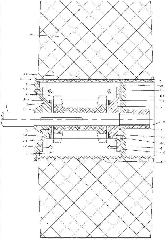
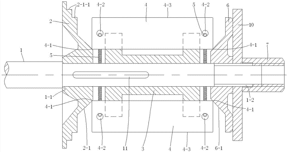
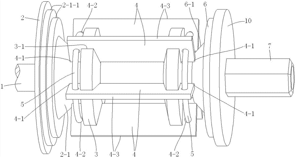
[0023] see Figure 1 to Figure 9 The yarn bobbin fixing device shown includes a rotating shaft 1, the yarn bobbin 8 is cylindrical and has a yarn 9 wound on its outer circular wall surface, and the rotating shaft 1 is placed in the inner hole of the yarn bobbin 8 In 8-1, when working, the yarn bobbin 8 rotates together with the rotating shaft 1, and the yarn 9 is pulled out from the yarn bobbin 8, so as to realize the unwinding of the yarn. The yarn bobbin fixing device also includes a first Expansion block 2, guide block 3, expansion sheet 4, ring spring 5, second expansion block 6 and tightening nut 7; one end shaft of the rotating shaft 1 is provided with a step surface 1-1, and the other end shaft of the rotating shaft 1 There is a threaded section 1-2 on the body, and the tightening nut 7 is screwed on the threaded section 1-2; the first expansion block 2 is a hollow conical frustum with a conical surface 2-1, and the first The expansion block 2 is set on the rotating sh...


PUM


Abstract

The invention discloses a bobbin fixing device. The bobbin fixing device comprises a rotating shaft, a first expansion block, a guide block, expansion pieces, ring springs, a second expansion block and a tightening nut. One end of the rotating shaft is provided with a step surface, and the other end of the rotating shaft is provided with a threaded section. The tightening nut is screwed on the threaded section. Both the first expansion block and the second expansion block are of a hollow cone frustum with a conical surface. The first expansion block is sleeved on the rotating shaft, and one end of the first expansion block is abutted against the step surface of the rotating shaft. The second expansion block is sleeved on the rotating shaft, and one end of the second expansion block is abutted against the tightening nut. The guide block is arranged between the first expansion block and the second expansion block, and at least three grooves are formed in the guide block, wherein the grooves extend along the rotating shaft axially and are evenly distributed along the rotating shaft circumferentially. The expansion pieces are plate-like rectangular solids, at least three in number and respectively embedded in the grooves of the guide block in a sliding and matched mode, the bottom ends of two sides of each expansion piece are respectively abutted against the conical surfaces of the first expansion block and the second expansion block, through holes are formed in the expansion pieces, and the ring springs penetrate through the through holes to connect the expansion pieces together. By means of the bobbin fixing device, a bobbin does not slip in the process of backing-off, and the bobbin fixing device can be adapted to large bobbins with high speeds and inclination angles.

Description

technical field [0001] The invention relates to a yarn bobbin fixing device used on a creel in textile equipment such as a warping machine or a warp knitting machine, and belongs to the technical field of textiles. Background technique [0002] The existing yarn bobbin fixing device used in textile equipment such as warping machines or warp knitting machines is mainly composed of a rotating shaft, a connecting seat and a swing arm. yarn, the rotating shaft is rotatably installed on the creel through bearings, and a section of the outer peripheral surface of the rotating shaft is a tapered surface. When the warping machine or warp knitting machine is working, put the yarn bobbin on the rotating shaft, and the conical surface section on the rotating shaft is placed in the inner hole of the yarn bobbin and closely fits with the inner hole of the yarn bobbin, which can ensure that the yarn bobbin and the rotating shaft When rotating together at a low speed to realize yarn unwin...

Claims


Application Information

Patent Timeline
Patent Type & Authority Patents(China)
IPC IPC(8): B65H54/547
Inventor 王占洪朱晓宏商汉东周杰
Owner CHANGZHOU RUNYUAN WARP KNITTING MACHINERY
Why Eureka
Try Eureka