Drive system for an electro-mechanical three-way dual seat valve

A double-seat valve and three-way technology, which is applied in the field of screw drive system for valve actuation, reciprocating three-way double-seat valve, and coolant valve, to eliminate seal leakage and seal wear, high fluid flow coefficient, and provide Effect of Fluid Flow Coefficient

Inactive Publication Date: 2013-05-08
GM GLOBAL TECH OPERATIONS LLC
View PDF5 Cites 4 Cited by
  • Summary
  • Abstract
  • Description
  • Claims
  • Application Information

AI Technical Summary

Problems solved by technology

Pressure drop and energy consumption are the main disadvantages of this type of valve

Method used


Image

  • Drive system for an electro-mechanical three-way dual seat valve
  • Drive system for an electro-mechanical three-way dual seat valve
  • Drive system for an electro-mechanical three-way dual seat valve

Examples


Embodiment Construction

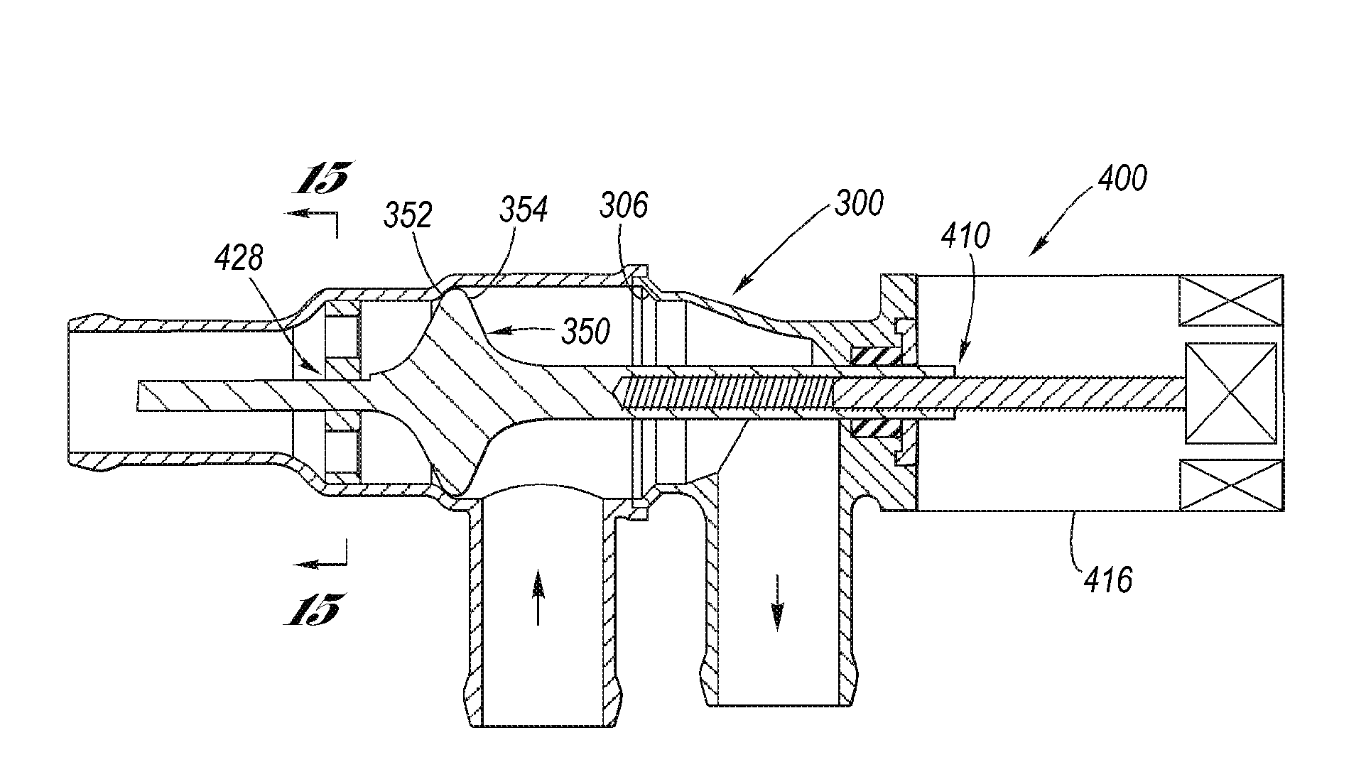
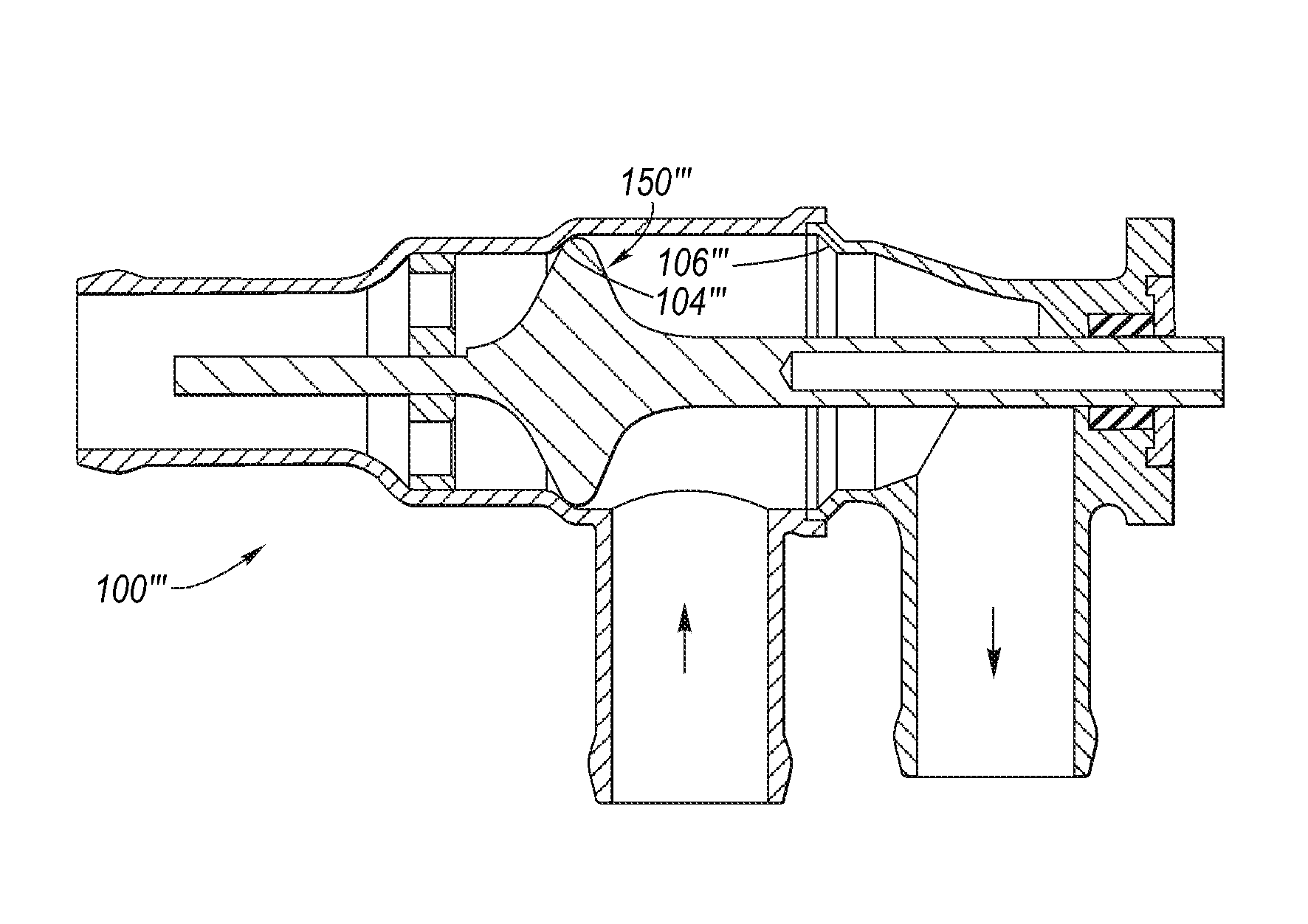
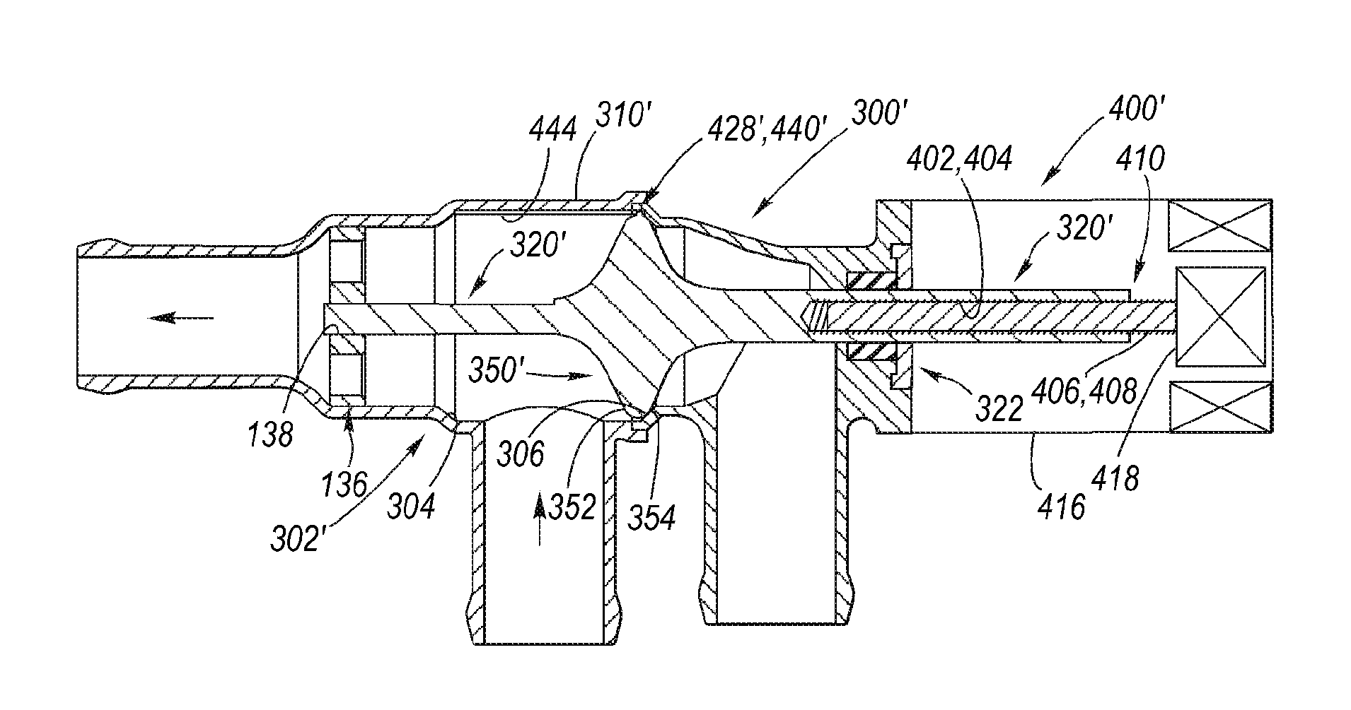
[0082] Referring now to the accompanying drawings, Figure 1 to Figure 12 Various exemplary aspects of the structure and function of a three-way double-seat valve are depicted, Figure 13 to Figure 21 Various exemplary aspects of a lead screw drive system according to the present invention for a three-way double-seat valve are depicted.

[0083] First refer to Figure 1 to Figure 12 , and now the three-way double-seat valve 100 will be described in detail. This Three-Way Dual Seat Valve 100 is described as "Electro-Mechanical Three-Way Dual Seat Valve" filed on November 1, 2011 by the applicant K.R. Kabel and assigned to its assignee US Patent Application Serial No. 13 / 286,452, the disclosure of which is incorporated herein by reference.

[0084] The three-way double-seat valve according to the present invention comprises a valve body 102; for manufacturing purposes, the valve body 102 is composed of first and second valve body parts 102', 102'', the first and second valve ...


PUM


Abstract

A three-way dual seat valve having a valve body including mutually spaced apart annular first and second valve seats. Reciprocally mounted with respect to the valve body is a dual-faced valve stem gate, wherein each gate face thereof is sealingly engageable with a respective valve seat in response to reciprocal movement of the valve stem gate effected via a leadscrew drive system.

Description

[0001] Cross References to Related Applications [0002] This application is a continuation-in-part of currently pending Serial No. 13 / 286,452 filed November 1, 2011. technical field [0003] The present invention relates to valves, including coolant valves commonly used in automotive applications. More specifically, the present invention relates to a reciprocating three-way double-seat valve. More specifically, the present invention relates to a lead screw drive system for providing valve actuation. Background technique [0004] Valves are ubiquitous in fluid flow systems to provide directional control of fluid flowing in the valves. A valve is used to open and close the direction of fluid flow, wherein the valve can function between a fully open state and a fully closed state, or can be progressive, wherein the open state is selectively between a fully open state and a fully closed state somewhere to meter fluid flow. The valve may be a two-way valve, controlling fluid...

Claims


Application Information

Patent Timeline
Patent Type & Authority Applications(China)
IPC IPC(8): F16K11/044F16K31/50F16K31/02
CPCF16K11/044F16K31/508
Inventor K.R.卡贝尔S.F.夏平B.D.帕雷赫
Owner GM GLOBAL TECH OPERATIONS LLC
Why Eureka
Try Eureka