Inspection equipment for wire rope

A technology for inspection devices and steel wire ropes, applied in transportation and packaging, textiles and papermaking, and manipulating parts, etc., can solve problems such as changes, confusing measurement results, and difficult applications

Inactive Publication Date: 2013-05-08
HITACHI LTD +1
View PDF6 Cites 11 Cited by
  • Summary
  • Abstract
  • Description
  • Claims
  • Application Information

AI Technical Summary

Problems solved by technology

[0012] However, in the case of detecting the torsion of the wire rope using the leakage magnetic flux as in the technique of Patent Document 1, when a relative motion between the measuring device (damage detector) and the wire rope occurs, the measurement

Method used


Image

  • Inspection equipment for wire rope
  • Inspection equipment for wire rope
  • Inspection equipment for wire rope

Examples


Embodiment 1

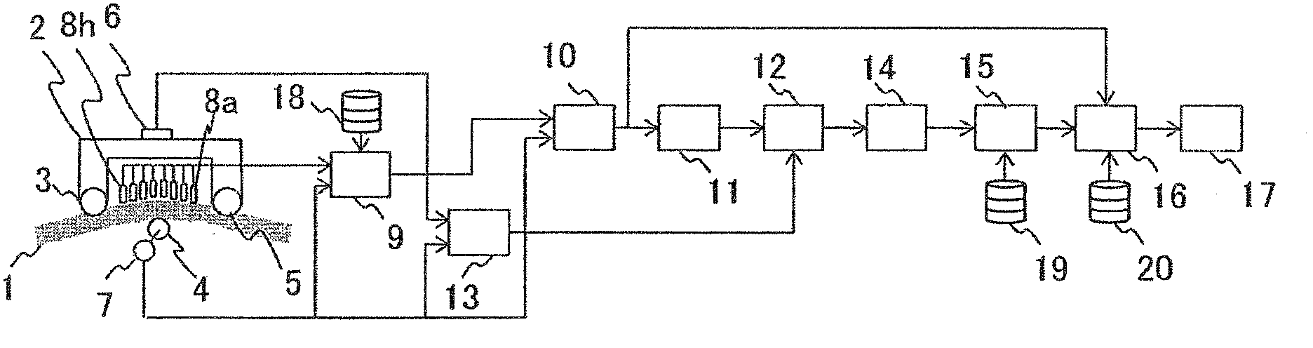
[0054] figure 1 It is a block diagram showing the basic configuration of the inspection device for the wire rope 1 according to the first embodiment of the present invention.

[0055] The inspection device for the steel wire rope 1 according to Embodiment 1 includes: a magnetizer 2 as a magnetization unit for magnetizing the steel wire rope 1 formed by twisting a bundle of a plurality of steel wires in the longitudinal direction; and a plurality of magnetic sensors as a magnetic detection unit. 8a to 8h, which are equipped close to the wire rope 1 and detect the leakage magnetic flux in the wire rope 1 magnetized by the magnetizer 2; , and the leakage flux detected by the magnetic sensors 8a-8h to calculate the rope pitch, and correct the elongation of the steel wire rope 1 based on the tension according to the calculated rope pitch, and on this basis, calculate the torsion of the steel wire rope 1.

[0056] Specifically, the inspection device uses a magnetizer 2 to magnetize...

Embodiment 2

[0079] Figure 8 It is a block diagram showing the basic configuration of the inspection device for the wire rope 1 according to the second embodiment of the present invention. The inspection device involved in embodiment 2 is in figure 1 On the basis of the inspection device related to the illustrated embodiment 1, instead of using the torsion amount converter 15 based on the initial torsion rate of the wire rope 1 stored in the storage device 19, the torsion rate from the filter 14 (measured Twist rate) is changed to the twist amount of each pitch, and the twist rate from the filter 14 (measured twist rate ) is changed as the function of the amount of twist for each pitch, and other parts are common to those of Embodiment 1. That is, the inspection device according to the second embodiment differs from the case of the first embodiment in the calculation method of the twist amount of the twist amount converter 15 .

Embodiment 3

[0081] The inspection device for the steel wire rope 1 according to Embodiment 3 of the present invention is figure 1 The application of the inspection device involved in the shown embodiment 1 Figure 8 The structure of the inspection device related to the shown embodiment 2 uses figure 1 In the illustrated configuration, the output of the storage device 18 is connected to the twist converter 15 . According to the above configuration, the inspection device according to the third embodiment can arbitrarily switch between the initial twist rate of the wire rope 1 using the storage device 19 and the use of the storage device 18 when calculating the twist amount by the twist amount converter 15 . The processing mode in the case of the design value of the twist pitch of the wire rope 1 is used.


PUM


Abstract

An inspection equipment to detect twist of a wire rope with high precision by taking influences of change in the rope pitch due to the relative movement between the rope and the inspection equipment and tension of the rope into consideration, a magnetization device (2) magnetizes a wire rope (1) in a longitudinal direction thereof, the wire rope being produced by twisting steel wire bundles; magnetic detectors (8a-8h) disposed near the wire rope detect magnetic flux leakage from the wire rope, an arithmetic unit calculates (9,10,11) a rope pitch using a relative velocity between the wire rope and the inspection equipment from an encoder (7) and the magnetic flux leakage and corrects (12) elongation of the rope due to the tension measured by a tension measurement unit (6,13) based on the calculated pitch to thereby calculate (14,15) twist of the rope, and supplies results of the calculation to determine acceptability or inacceptability of the rope (16,17).

Description

technical field [0001] The present invention relates to an inspection device of a steel wire rope, which is used, for example, in elevators, cranes, etc., and is constituted by twisting bundles of steel wires. Background technique [0002] Conventionally, such wire ropes have been constructed by twisting bundles of a plurality of thin steel wires (monofilaments), and the wires are brought into contact with each other by twisting bundles of steel wires, so that the wire rope is formed so that not only the axial force of the single wires has an effect on the suspension load. Contributed, friction between monofilaments also contributes to the suspension load structure. In general, the force applied to each monofilament differs depending on the structure of the rope and the twisting method, and there are various kinds of ropes depending on the purpose. In addition, due to fatigue and wear of the steel wire rope, the steel wires of the constituent parts are sequentially broken. ...

Claims


Application Information

Patent Timeline
IPC IPC(8): G01N27/83
CPCG01N27/87B66B7/123D07B1/145D07B2301/251D07B2301/555G01N27/83
Inventor 浅井大辅大石照展伊东知彦
Owner HITACHI LTD
Why Eureka
Try Eureka