
Display device and electronic apparatus

A technology for display devices and display parts, applied in electrical components, optics, instruments, etc., can solve problems such as degradation of stereoscopic display quality, and achieve the effect of suppressing moiré fringes

Inactive Publication Date: 2013-05-08
SONY CORP
View PDF4 Cites 2 Cited by
  • Summary
  • Abstract
  • Description
  • Claims
  • Application Information

AI Technical Summary

Problems solved by technology

This can result in a loss of quality for stereoscopic displays

Method used


Image

  • Display device and electronic apparatus
  • Display device and electronic apparatus
  • Display device and electronic apparatus

Examples


no. 1 example

[0037] Example of display device of parallax barrier scheme

[0038] 2. The second embodiment

[0039] Example using multi-pixel structure

no. 3 example

[0041] Example of display device of lenticular lens scheme

[0042] 4. Other embodiments

[0043] Examples of electronic devices, etc.

[0044] [1. The first embodiment]

[0045] 【Basic configuration of the display device】

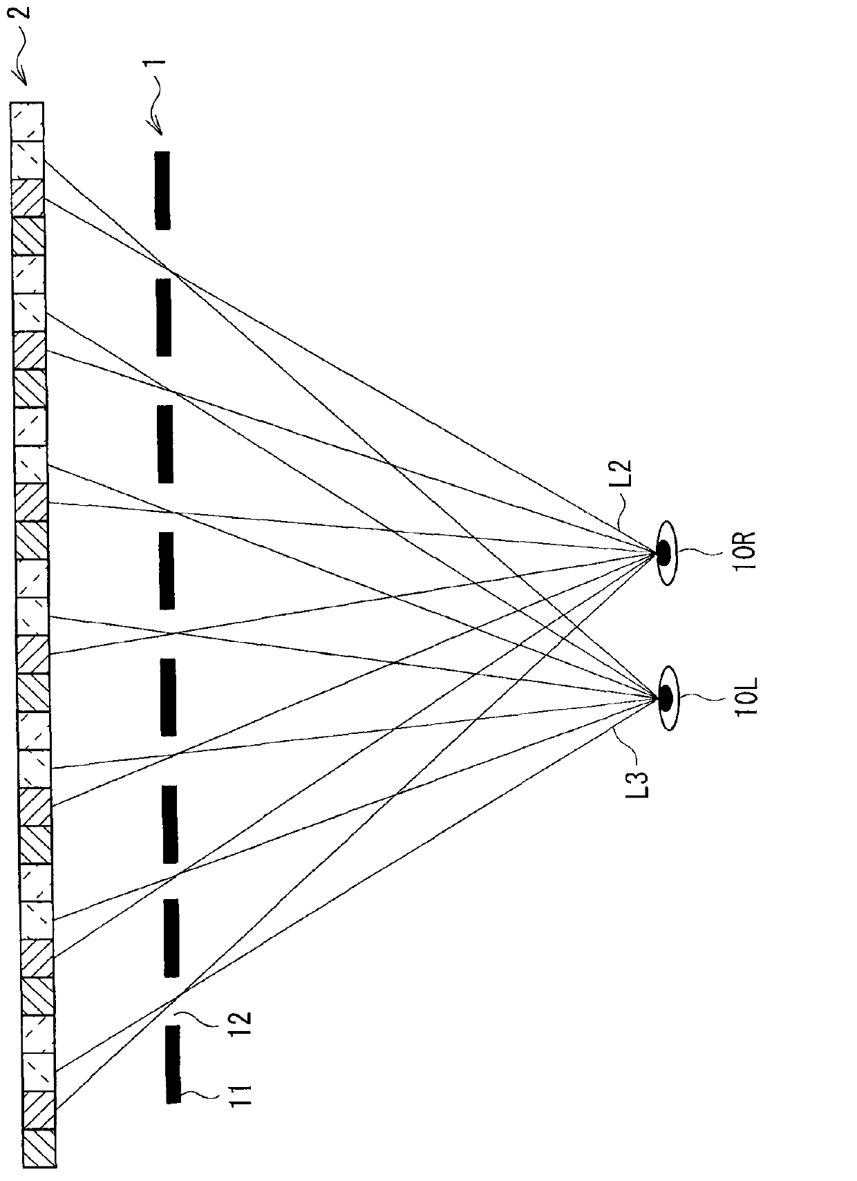
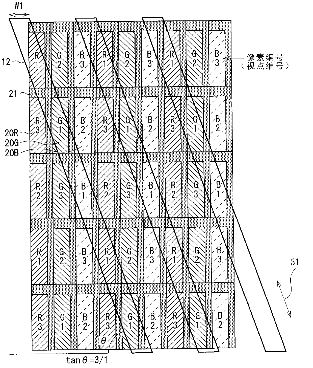
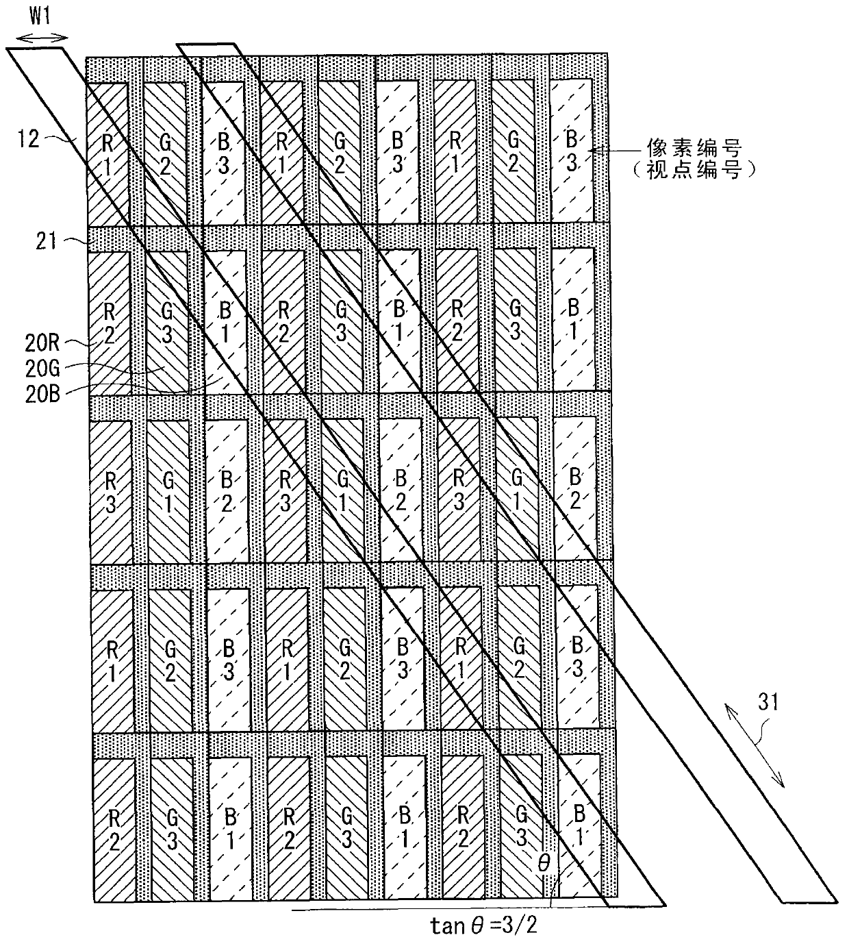
[0046] will refer to Figure 1 to Figure 4 The basic configuration of the display device according to the first embodiment of the present invention is described. The display device includes a parallax barrier 1 and a display section 2 .

[0047] The display unit 2 is constituted by a two-dimensional display (for example, a liquid crystal display panel, an electroluminescence scheme display panel, or a plasma display). The display section 2 includes, within its image display surface, a plurality of pixels arranged two-dimensionally in the horizontal direction and the vertical direction. Each pixel includes a plurality of sub-pixels.

[0048] For example, if Figure 2 to Figure 4 As shown in , each pixel includes sub-pixels having first to third colo...


PUM


Abstract

A display device includes: a display section including a plurality of pixels, the display section displaying a plurality of perspective images; and a plurality of separating sections each tilted in a first oblique direction, and each separating the perspective images displayed on the display section into different directions. Each of the pixels has a shape extending differently between in the first oblique direction and in a second oblique direction, the second oblique direction being tilted in a direction opposite to the first oblique direction with respect to a vertical direction.

Description

technical field [0001] The present application relates to a display device that performs stereoscopic display of a naked-eye scheme using a parallax barrier or the like, and an electronic device including such a display device. Background technique [0002] Methods of performing stereoscopic display include a glasses scheme that uses glasses (for stereoscopic vision) and a naked eye scheme that uses naked eyes to obtain stereoscopic vision without using special glasses for stereoscopic vision. Typical methods of the naked-eye scheme are the parallax barrier scheme and the lenticular lens scheme. In the parallax barrier scheme and the lenticular scheme, on a two-dimensional display panel, a plurality of perspective images (perspective images) for stereoscopic vision (in the case of two perspective images, respectively for the right eye and viewpoint image of the left eye), and the displayed viewpoint images are separated by a separator in the horizontal direction. Thereby o...

Claims


Application Information

Patent Timeline
IPC IPC(8): G02B27/22H04N13/04G02B30/31G02B30/32
CPCH04N13/04G02B27/22G02B27/2214H04N13/0409H04N13/0415G02F1/00G02F1/133512G02F1/136209H04N13/31H04N13/317G02B30/31G02B30/32G02B30/27
Inventor 井上雄一小日向真理子星野宪文
Owner SONY CORP
Learn More