Management method and accessing point of terminal and terminal

A terminal management and access point technology, applied in the communication field, can solve the problems of inconvenient AP centralized management, short monitoring period, and sensor power consumption, and achieve the effect of saving power

Active Publication Date: 2013-05-08
HUAWEI TECH CO LTD
View PDF4 Cites 38 Cited by
  • Summary
  • Abstract
  • Description
  • Claims
  • Application Information

AI Technical Summary

Problems solved by technology

[0005] However, in the sensor (English full name is sensor) scenario, the non-AP STA communicates with the AP as a sensor, and the sensor may need to communicate with the AP less often in a period of time, so there is no need to monitor the DTIM frequently. It will consume a lot of power of the sensor. In the prior art, the monitoring period set by the sensor for itself is generally relatively short. For example, 16 bits are used to represent the monitoring period. The monitoring period is based on the beacon period, and the beacon period is determined by the AP. , usually the beacon period unit is 1024us, so when the beacon period is 1024us, the longest interval for the sensor to monitor the beacon is 65536*1024us≈67s, that is, the existing sensor will monitor the beacon according to the 67s monitoring period, for many sensors This monitoring cycle is too frequent. For example, as a sensor on a household meter, it only needs to report the power consumption to the AP once a week or a month. Usually, it does not need to communicate with the AP. For sensors that do not need to communicate with the AP frequently The monitoring cycle set in the prior art consumes a lot of power of the sensor
In addition, in the prior art, the way in which the monitoring period is completely determined by the sensor is not convenient for the centralized management of the AP, and there is an urgent need to propose a new method for managing terminals (especially terminals used as sensors)

Method used


Image

  • Management method and accessing point of terminal and terminal
  • Management method and accessing point of terminal and terminal
  • Management method and accessing point of terminal and terminal

Examples


Embodiment Construction

[0048] Embodiments of the present invention provide a terminal management method, an access point, and a terminal, which are used to implement centralized management of the terminal by the access point, which is beneficial for the terminal to save power.

[0049] In order to make the purpose, features and advantages of the present invention more obvious and understandable, the technical solutions in the embodiments of the present invention will be clearly and completely described below in conjunction with the accompanying drawings in the embodiments of the present invention. Obviously, the following The described embodiments are only some, not all, embodiments of the present invention. All other embodiments obtained by those skilled in the art based on the embodiments of the present invention belong to the protection scope of the present invention.

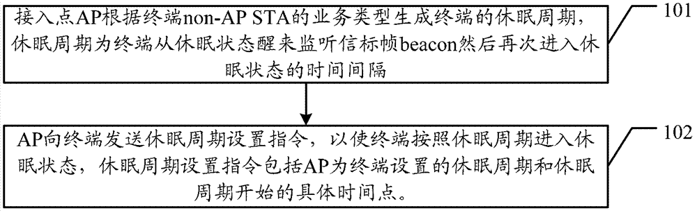
[0050] A terminal management method provided by an embodiment of the present invention, such as figure 1 shown, including:

[...


PUM


Abstract

The invention discloses a management method and an accessing point of a terminal and the terminal. The management method and the accessing point of the terminal and the terminal is used for realizing a centralized management of the terminal through an access point, thus being beneficial to saving the electric quantity of the terminal. The management method and the accessing point of the terminal and the terminal comprise the method that the access point (AP) generates a dormant period of the terminal according to the service type of non-AP static time series analysis (STA) of the terminal. The dormant period is a time interval which the terminal awakes from a dormant state to monitor a beacon frame (beacon), and then goes to the dormant state again. The AP sends a setting order of the dormant period to the terminal so as to enable the terminal to go to the dormant state according to the dormant period. The setting order of the dormant period comprises the dormant period which is set by the AP for the terminal and a specific time point which the dormant period starts.

Description

technical field [0001] The present invention relates to the field of communication technology, in particular to a terminal management method, an access point and a terminal. Background technique [0002] According to the Institute of Electrical and Electronics Engineers (IEEE, Institute of electrical and electronics engineers) 802.11ac agreement: Basic Service Set (BSS, Basic Service Set) is a station (STA, Station )composition. In the BSS network, there is only one central site with a full-time management BSS called the access point (AP, AccessPoint), while other sites in the BSS network that are not APs are called terminals, also called non-access points Site (abbreviated as non-AP STA in English). [0003] The non-AP STA residing under an AP sets a monitoring period by itself, receives the beacon frame (called beacon in English) sent by the AP according to the monitoring period, and monitors whether the AP has downlink data sent to the non-AP STA. The AP can coordinate...

Claims


Application Information

Patent Timeline
Patent Type & Authority Applications(China)
IPC IPC(8): H04W48/10H04W52/02
CPCY02D30/70
Inventor 陈庆勇夏林峰刘孟红
Owner HUAWEI TECH CO LTD
Why Eureka
Try Eureka