
Circuit assembly and method for operating at least one LED

A technology of circuit devices and control devices, applied to lighting devices, electric light sources, electrical components, etc., to achieve the effect of avoiding optical effects

Inactive Publication Date: 2013-05-08
OSRAM GMBH
View PDF3 Cites 4 Cited by
  • Summary
  • Abstract
  • Description
  • Claims
  • Application Information

AI Technical Summary

Problems solved by technology

However, the method described has the disadvantage that when changing the dimming angle, the light color of the light output by the at least one LED is also changed

Method used


Image

  • Circuit assembly and method for operating at least one LED
  • Circuit assembly and method for operating at least one LED

Examples


Embodiment Construction

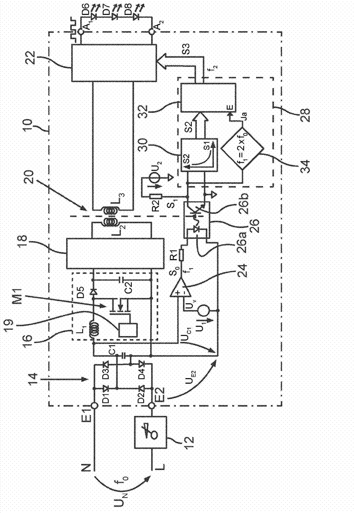
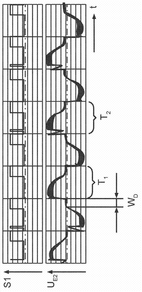
[0024] figure 1A schematic diagram of an exemplary embodiment of a circuit arrangement 10 according to the invention is shown. The circuit arrangement 10 has an input with a first input connection E1 and a second input connection E2 . Input terminal E1 and supply voltage U N The first phase N of the coupling, while the second input E2 is connected to the supply voltage U N The phase L coupling. Power supply voltage U N can especially have a frequency f of 50 Hz or 60 Hz 0 . The dimming angle is adjusted by means of the phase dimmer 12, that is to say the duration is determined within which the voltage at the supply voltage U N A preset range of cycles is maintained at 0V. When the cycle duration is 360°, then the dimming angle W D Values ​​in the range between 0° and 180° can be considered. The phase dimmer 12 can have an interface via which the dimming angle can be adjusted manually or electronically.

[0025] An input of a rectifier 14 comprising diodes D1 , D2 , D...


PUM


Abstract

The invention relates to a circuit assembly for operating at least one LED (D6, D7, D8), the assembly being designed to use alternating supply voltage (UN) modified by a phase dimmer (12) for adjusting a dimming angle (WD) for dimming the at least one LED (D6, D7, D8). For this purpose, a controllable current source (22) is provided, which is designed such that at the output thereof a PWM signal to the at least one LED (D6, D7, D8) is provided. Said controllable current source (23) is provided with a control input to which a PWM signal (S3) having a second frequency (f2) is supplied, wherein said signal is derived from a PWM signal (SO) having a first frequency (f1), the pulse width of which is correlated to the dimming angle (WD) adjusted by the phase dimmer (12). The invention further relates to a corresponding method for operating at least one LED (D6, D7, D8).

Description

technical field [0001] The invention relates to a circuit arrangement for driving at least one LED, said circuit arrangement having an input and a rectifier, wherein said input has a first and a second input terminal for adjusting the dimming angle by means of a phase modulation The rectifier is coupled to a changed AC mains voltage, the rectifier having an input and an output, wherein the input of the rectifier is coupled to the input of the circuit arrangement. Furthermore, the invention relates to a corresponding method for operating at least one LED. In the following embodiments, the terms "dimming angle" and "phase angle" are used as synonyms. Background technique [0002] The present invention concerns the subject matter known under the term "retrofit device". The aim here is to replace incandescent or halogen lamps by lamps or lighting devices with LEDs. The reason for this is the higher efficiency and the longer service life of LEDs. Of particular interest in thi...

Claims


Application Information

Patent Timeline
Patent Type & Authority Applications(China)
IPC IPC(8): H05B33/08H05B44/00
CPCY02B20/347H05B33/0815Y02B20/30H05B45/38H05B45/382H05B45/39
Inventor 托马斯·波利斯昌斯基
Owner OSRAM GMBH
Learn More