Touch control display device

A touch display device and touch display technology are applied in the fields of instruments, electrical digital data processing, and data processing input/output processes, etc., and can solve problems such as weak structural strength, high risk of touch failure, and differences in optical properties. , to improve bending reliability, reduce the risk of low-temperature dry etching process, and avoid inconsistent optical effects

Active Publication Date: 2020-08-11
WUHAN CHINA STAR OPTOELECTRONICS SEMICON DISPLAY TECH CO LTD
View PDF14 Cites 2 Cited by
  • Summary
  • Abstract
  • Description
  • Claims
  • Application Information

AI Technical Summary

Problems solved by technology

This technology brings the following defects: the width of the bridging conduction point at the bridging position of the driving electrode 41 or the sensing electrode 42 is larger than the metal width at other positions, resulting in differences in the optical characteristics of the pixel light emission and the non-bridging position; the higher the touch accuracy , the more touch electrodes, the more metal bridging points, the more dry etching via sites in the process, and the etching depth of the display area and the bonding (pad-bonding) area are not the same, in order to ensure the uniformity of the via hole depth To realize the conduction of the touch electrodes is a great challenge to the low-temperature dry etching process, and the risk of touch failure is high. Especially in the high-generation panel line process, the risk of the low-temperature dry etching process has a greater impact on the yield; The structural strength of the bridging electrodes 43 and the via holes 31 is weak, and the risk of an open circuit in the folding screen is high

Method used


Image

  • Touch control display device
  • Touch control display device
  • Touch control display device

Examples


Embodiment Construction

[0040] The following will clearly and completely describe the technical solution in the application with reference to the accompanying drawings in the implementation manner of the application. Apparently, the described implementations are only some of the implementations of this application, not all of them. Based on the implementation manners in this application, all other implementation manners obtained by those skilled in the art without creative efforts shall fall within the scope of protection of this application.

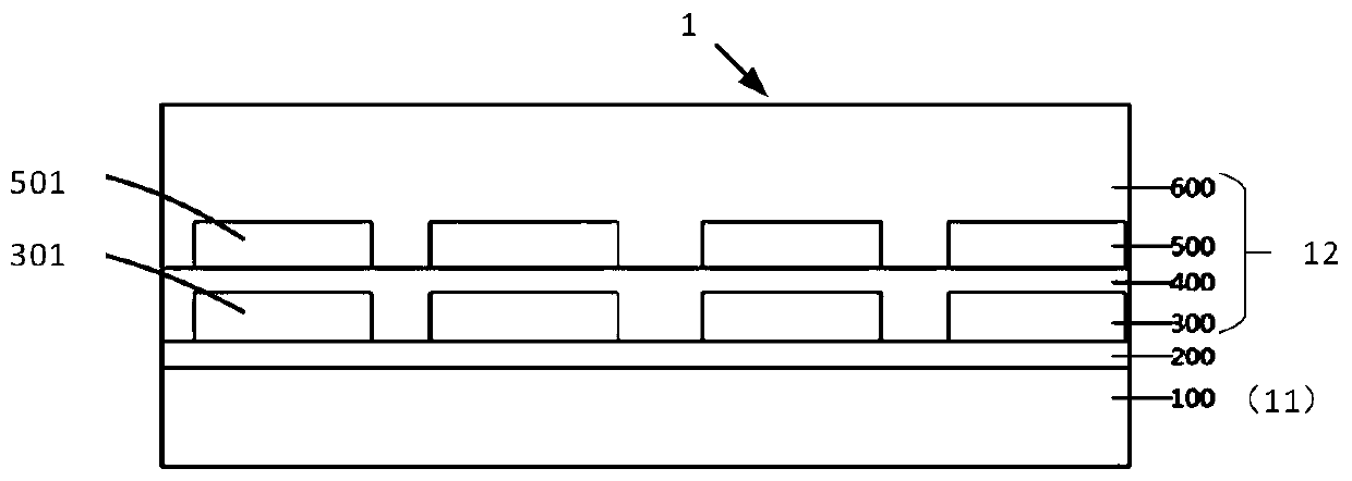
[0041] Please refer to figure 2 , the first embodiment of the present application provides a touch display device 1 , which includes a display module 11 and a touch module 12 . The display module 11 and the touch module 12 are stacked. Wherein, the display module 11 may be an active light-emitting display module, such as an organic light-emitting diode (OLED) display module, a micro-light-emitting diode (micro-LED) display module, or a submillimeter light-e...


PUM


Abstract

The invention provides a touch control display device which comprises a display module and a touch control module which are arranged in a stacked mode, and the touch control module comprises a first touch control electrode layer, a second touch control electrode layer and an insulating layer located between the first touch control electrode layer and the second touch control electrode layer whichare arranged in a stacked mode. The touch control display device is provided with a touch control display area and a binding area located on one side of the touch control display area, a plurality ofwelding pads are arranged in the binding area, and the welding pads are arranged on the second touch control electrode layer; the first touch control electrode layer comprises a first touch electrodeand a first lead connected to the first touch electrode; the second touch control electrode layer comprises a second touch control electrode and a second lead connected to the second touch electrode;the first lead extends to the binding area from the first touch electrode and extends to the second touch control electrode layer through a via hole formed in the insulating layer to be electrically connected with the welding pad, and the second lead extends to the binding area from the second touch electrode to be electrically connected with the welding pad.

Description

technical field [0001] The present application relates to the display field, in particular to a touch display device. Background technique [0002] Organic light-emitting diode On-cell touch display (OLED On-cell Touch) technology, also known as DOT technology (Direct On-Cell Touch), integrates organic light-emitting diode display panels and touch structures. Panel) technology has the advantages of higher transmittance, bending resistance, and thinness, and has become the future trend of flexible OLED display. This technology is to directly use a low-temperature process (temperature less than or equal to 90°C) to make a touch structure on the Thin-Film Encapsulation (TFE) of the OLED panel, so as to realize the integration of the OLED and the Touch structure. The structure of a known DOT touch display panel is as follows: figure 1 As shown, the OLED panel 10 , the TFE encapsulation layer 20 , the insulating layer 30 and the touch module 40 are stacked in sequence. The tou...

Claims


Application Information

Patent Timeline
Patent Type & Authority Applications(China)
IPC IPC(8): G06F3/041G06F3/047
CPCG06F3/0412G06F3/047G06F2203/04103G06F2203/04102G06F3/0445G06F3/0446G06F2203/04112
Inventor 李远航
Owner WUHAN CHINA STAR OPTOELECTRONICS SEMICON DISPLAY TECH CO LTD
Why Eureka
Try Eureka