Cylindrical workpiece stepped sliding chute feed device

A technology of a feeding device and a cylinder is applied in the field of a cylindrical workpiece step chute feeding device, which can solve the problems of the difficult cylindrical workpiece flowing out in the lateral state, and the inability to solve the problems of the cylindrical workpiece and single feeding.

Inactive Publication Date: 2013-05-15
CHONGQING JUKANG BUILDING MATERIAL
View PDF0 Cites 4 Cited by
  • Summary
  • Abstract
  • Description
  • Claims
  • Application Information

AI Technical Summary

Problems solved by technology

Although the chute feeding device in the prior art can meet the conveying requirements of some workpieces to a certain extent, it still has the following deficiencies in the actual use process: 1. It cannot solve the problem of feeding a batch of cylindrical workpieces individually.
2. It is difficult to keep the cylindrical workpiece that is fed into the chute horizontally and flow out in a horizontal state

Method used


Image

  • Cylindrical workpiece stepped sliding chute feed device

Examples


Embodiment Construction

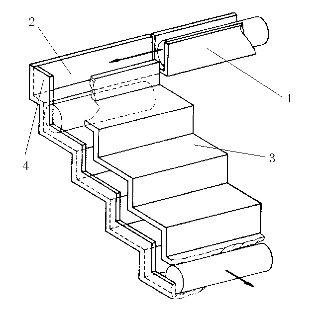
[0010] Such as figure 1 The present invention relates to a cylindrical workpiece step chute feeding device. In order to solve the above technical problems, the present invention provides the following technical solutions: a cylindrical workpiece step chute feeding device, including a feeding conveying device and an output device, feeding The conveying device is a laterally arranged feeding chute 1; the output device includes a stepped slide 2 and a step cover 3 located on the stepped slide 2. The shape of the stepped slide 2 and the shape of the stepped cover 3 are matched with each other, and the two are formed A stepped cavity, the size of the cavity is the same as the size of the workpiece; the bottom surface of the feeding chute 1 and the first step surface of the stepped chute 2 are located on the same plane and they are close to each other. A baffle 4 perpendicular to the step surface of the step slide 2 is provided on the side of the step slide 2 opposite to the feed chu...


PUM


Abstract

The invention belongs to the field of workpiece convey, and particularly relates to a cylindrical workpiece stepped sliding chute feed device. The cylindrical workpiece stepped sliding chute feed device comprises a feed convey device and an output device. The feed convey device is a horizontally-arranged feed sliding chute. The output device comprises a stepped sliding rail and a stepped cover arranged on the stepped sliding rail, and a stepped cavity is formed between the stepped sliding rail and the stepped cover and is equal to a workpiece in size. The bottom surface of the feed sliding chute and a first step surface of the stepped sliding rail are arranged on the same plane and are close to each other. According to the cylindrical workpiece stepped sliding chute feed device, the workpiece can flow out in a horizontal state, and workpieces can be fed in a single mode.

Description

Technical field [0001] The invention belongs to the field of workpiece conveying, and particularly relates to a cylindrical workpiece step chute feeding device. Background technique [0002] In current industrial production, chute feeding devices are widely used for workpiece transportation. Although the chute feeding device in the prior art can meet the transportation requirements of some workpieces to a certain extent, it still has the following shortcomings in actual use: 1. It cannot solve the problem of feeding a batch of cylindrical workpieces individually. 2. It is difficult to keep the cylindrical workpiece fed into the chute horizontally and flow out in a horizontal state. Summary of the invention [0003] The purpose of the present invention is to provide a cylindrical workpiece step chute feeding device that can maintain the lateral state of the workpiece and can be fed individually. [0004] In order to solve the above technical problems, the present invention provides...

Claims


Application Information

Patent Timeline
IPC IPC(8): B65G11/02B65G11/08B65G11/20
Inventor 周炫张信聪
Owner CHONGQING JUKANG BUILDING MATERIAL
Why Eureka
Try Eureka