Shockproof card type wireless positioning terminal with cell limiting function

A wireless positioning, card-type technology, applied in wireless communication, battery pack components, circuits, etc., can solve the problems of wireless positioning terminal battery disconnection, equipment damage, etc., to improve product assembly efficiency and avoid mechanical impact.

Inactive Publication Date: 2013-05-22
CHENGDU RUIYI INFORMATION TECH
View PDF3 Cites 3 Cited by
  • Summary
  • Abstract
  • Description
  • Claims
  • Application Information

AI Technical Summary

Problems solved by technology

[0006] However, if the battery is set in the above way, when the wireless positioning terminal vibrates or falls, the battery of the wireless positioning terminal will be disconnected and the equipment will be damaged.

Method used


Image

  • Shockproof card type wireless positioning terminal with cell limiting function
  • Shockproof card type wireless positioning terminal with cell limiting function
  • Shockproof card type wireless positioning terminal with cell limiting function

Examples


Embodiment 1

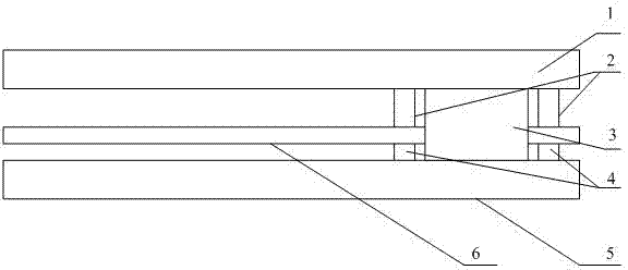
[0026] The shockproof card-type wireless positioning terminal with battery limit is mainly composed of an upper cover 1 and a lower cover 5, and a circuit board 6 arranged between the upper cover 1 and the lower cover 5. The circuit board 6 is provided with a battery hole. A battery 3 is installed in the battery hole.

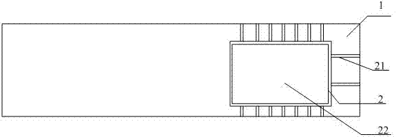
[0027] The side of the upper cover 1 close to the circuit board 6 is provided with upper cover limiting ribs 2 , and the upper cover limiting ribs 2 are arranged around the four side walls of the battery 3 and form an upper cover limiting groove 22 .

[0028] The upper cover limiting ribs 2 are also connected with several upper ribs 21 , the ends of the upper ribs 21 away from the upper cover limiting ribs 2 extend to the edge of the upper cover 1 , and the upper ribs 21 are connected with the upper cover 1 .

[0029] The distance between the upper cover limiting rib 2 and the four side walls of the battery 3 is 0 mm to 1 mm.

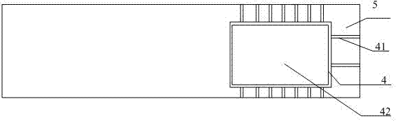
[0030] The side of the lower cov...

Embodiment 2

[0037] In order to ensure that the battery 3 is not affected by the vibration, the battery 3 is damaged. Because what the present invention designs is a sealed dust-proof design. Therefore, if the battery 3 is damaged, it will be very troublesome to replace the new battery 3. In order to reduce the probability of the battery 3 being damaged, the present invention is specially arranged at the bottom of the upper cover limit groove 22 and the bottom of the lower cover limit groove 42. An upper shockproof cushion 23 and a shockproof cushion 24 are respectively provided. Using the upper shockproof cushion 23 and the shockproof cushion 24.3 in this way can make the upper and lower surfaces of the battery have buffer barriers when they contact the upper cover 1 and the lower cover 5 . In this way, the probability of battery 3 being damaged is reduced.

[0038] As described above, the present invention can be well realized.


PUM


Abstract

The invention discloses a shockproof card type wireless positioning terminal with a cell limiting function. The terminal mainly comprises an upper cover, a lower cover and a circuit board which is arranged between the upper cover and the lower cover, wherein a cell hole is formed in the circuit board, and a cell is installed inside the cell hole. The terminal has the advantages that firstly, an upper cover limiting rib and a lower cover limiting rib are used for limiting the X direction and the Y direction of the cell, the cell can be installed in place quickly, and the product assembly efficiency is improved; secondly, the upper cover limiting rib and the lower cover limiting rib are used for limiting the moving distance of the cell when a product falls down and vibrates, and the cell mechanical shock caused by external moving and falling changes is avoided; and thirdly, the breaking risk due to cell moving is avoided during cell welding.

Description

technical field [0001] The invention relates to a wireless positioning terminal, in particular to a card type wireless positioning terminal which is shockproof and equipped with a battery limit. Background technique [0002] The existing wireless positioning terminal includes upper and lower casings, and a PCB circuit board arranged between the upper and lower casings. [0003] Wherein, the PCB circuit board includes a battery. [0004] In the existing wireless positioning terminal, the battery is provided with a special battery frame, but after the battery frame is installed in the existing wireless positioning terminal, the thickness of the wireless positioning terminal will inevitably be increased. [0005] Therefore, in the improved wireless positioning terminal, in order to reduce the thickness of the wireless positioning terminal, the battery is directly connected to the circuit board in the wireless positioning terminal by welding. No battery frame is set. [0006]...

Claims


Application Information

Patent Timeline
IPC IPC(8): H01M2/10H04W88/02
CPCY02E60/12Y02E60/10
Inventor 任佳
Owner CHENGDU RUIYI INFORMATION TECH
Why Eureka
Try Eureka