
An apparatus for performing a plasma chemical vapour deposition process

A chemical vapor deposition and plasma technology, which is applied in gaseous chemical plating, electrical components, manufacturing tools, etc., can solve the problems of temporary attenuation or even disappearance of plasma, high power consumption, etc.

Active Publication Date: 2013-05-29
DRAKA COMTEQ BV
View PDF6 Cites 2 Cited by
  • Summary
  • Abstract
  • Description
  • Claims
  • Application Information

AI Technical Summary

Problems solved by technology

The breakdown process consumes a lot of power, which means that the plasma itself may temporarily decay or even disappear, which has negative consequences for any product made through the plasma process

Method used


Image

  • An apparatus for performing a plasma chemical vapour deposition process
  • An apparatus for performing a plasma chemical vapour deposition process
  • An apparatus for performing a plasma chemical vapour deposition process

Examples


Embodiment Construction

[0016] It should be noted that the drawings only show preferred embodiments according to the invention. In the drawings, the same reference numerals denote the same or corresponding parts.

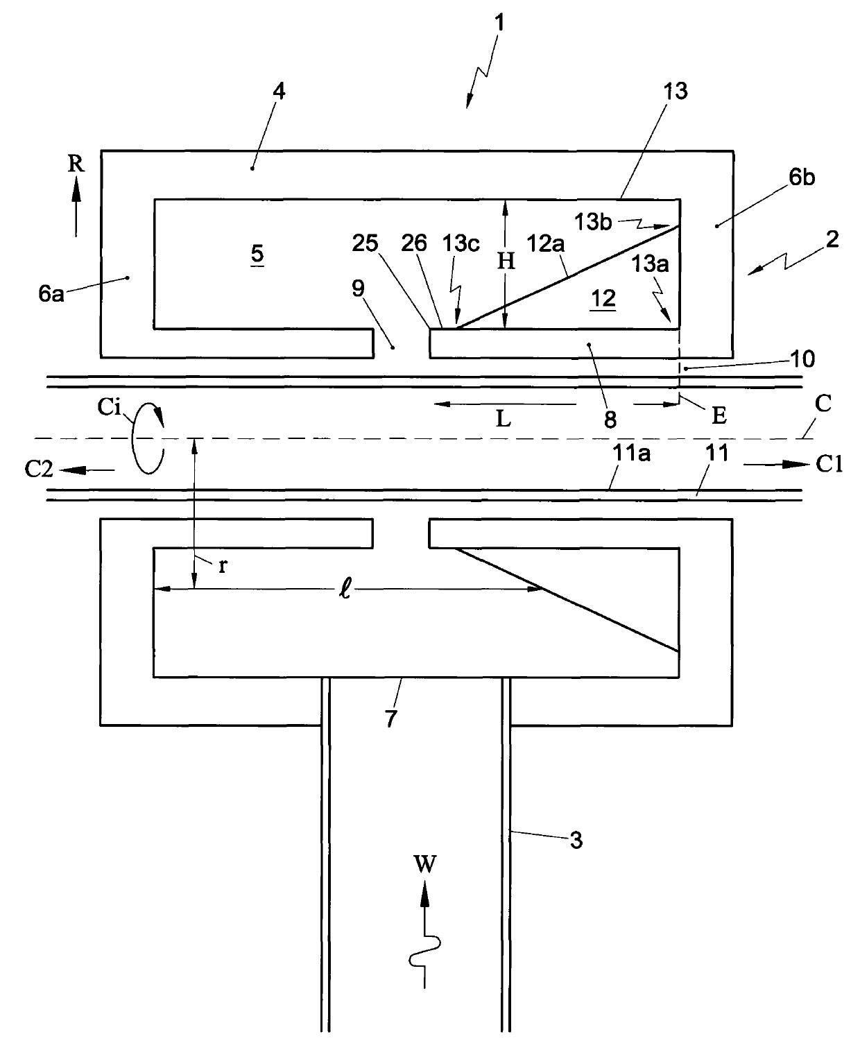
[0017] figure 1 A schematic cross-sectional side view of a first embodiment of the device 1 according to the invention is shown. The device 1 comprises a substantially cylindrical resonator 2 . The device also includes a microwave waveguide 3 that guides microwaves to the resonator 2 . The microwave waveguide 3 is preferably rectangular, so that an optimal interface can be formed between the waveguide 3 and the resonator 2 . The device can be used to perform a plasma chemical vapor deposition process.

[0018] The resonator 2 is provided with a cylindrical outer wall 4 surrounding a resonator cavity 5 . The cavity has a substantially rotationally symmetrical shape with respect to the axis C of the cylinder. The resonator 2 is also provided with side wall portions 6a, 6b delimiting th...


PUM


Abstract

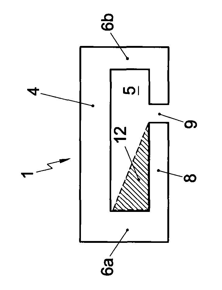
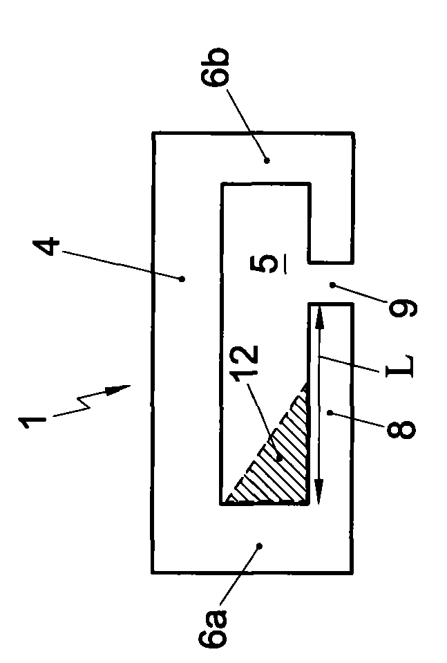
The invention relates to an apparatus for performing a plasma chemical vapour deposition process. The apparatus comprises a mainly cylindrical resonator being provided with an outer cylindrical wall enclosing a resonant cavity having a substantially rotational symmetric shape with respect to a cylindrical axis. The resonator further includes side wall portions bounding the resonant cavity in opposite cylindrical axis directions. In addition, the apparatus comprises a microwave guide extending through the outer cylindrical wall into the resonant cavity. The length of the resonant cavity in the cylindrical direction varies as a function of the radial distance to the cylindrical axis.

Description

technical field [0001] The present invention relates to a device for performing a plasma chemical vapor deposition process comprising a substantially cylindrical resonator provided with a cylindrical outer wall surrounding a resonant cavity having a substantially rotational axis with respect to the cylinder axis Symmetrical in shape, the resonator is also provided with side wall portions confining the resonant cavity along opposite cylindrical axis directions, wherein the device further includes a microwave waveguide portion, one end of which extends through the cylindrical outer wall into the resonant cavity. Background technique [0002] European Patent Publication EP 1867610 in the name of Draka Comteq B.V. discloses such an apparatus for manufacturing optical fibers. [0003] When high power microwaves are applied to long duration processes, problems with load matching can arise due to internal reflections and susceptibility to arcing. If the loads are not matched, the ...

Claims


Application Information

Patent Timeline
IPC IPC(8): C23C16/44H01P7/06
CPCC23C16/511H01J37/32256H01J37/32229C03B37/0183C03B37/018
Inventor M·J·N·范斯特拉伦I·米利塞维克J·A·哈特苏伊克
Owner DRAKA COMTEQ BV
Learn More