Sewing machine

A sewing machine and moving mechanism technology, applied in the field of sewing machines, can solve problems such as difficulty in ensuring the installation space of Y-axis moving components

Active Publication Date: 2013-06-05
BROTHER KOGYO KK
View PDF4 Cites 7 Cited by
  • Summary
  • Abstract
  • Description
  • Claims
  • Application Information

AI Technical Summary

Problems solved by technology

In existing sewing machines, it is difficult to ensure the installation space of the Y-axis moving member due to the narrow space above the lower shaft.

Method used


Image

  • Sewing machine
  • Sewing machine
  • Sewing machine

Examples


Embodiment Construction

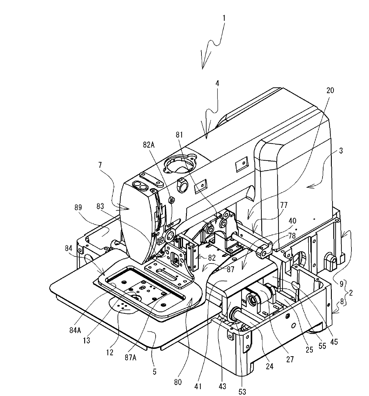
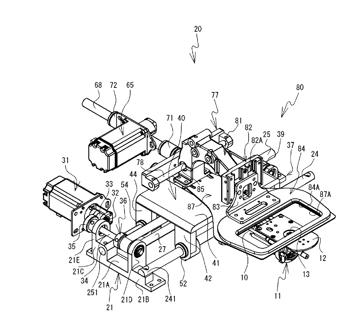
[0023] One embodiment of the present invention will be described with reference to the drawings. Will figure 1 The left obliquely lower, right obliquely upper, left obliquely upper, and right obliquely lower are defined as the front, rear, left, and right of the sewing machine 1, respectively. Will image 3 The lower right, the upper left, the lower left, and the upper right are defined as the front, the rear, the left, and the right of the cloth feeding drive device 20, respectively. The X-axis direction is the left-right direction of the sewing machine 1 and the cloth feed driving device 20 . The Y-axis direction is the front-back direction of the sewing machine 1 and the cloth feed drive device 20 .

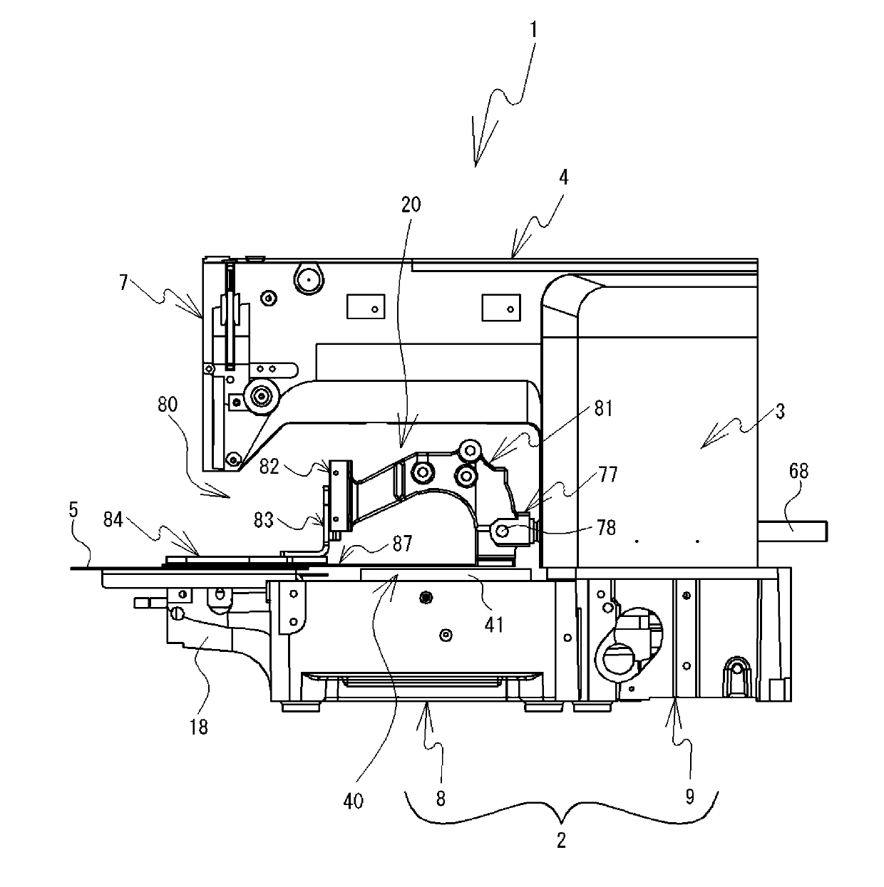
[0024] refer to figure 1 , figure 2 The structure of the sewing machine 1 will be described. The sewing machine 1 includes a base portion 2 , a pillar portion 3 , and an arm portion 4 . The base part 2 includes a front part 8 and a rear part 9 . The front part 8 and t...


PUM


Abstract

The invention provides a sewing machine which can arrange one of fixed rails extending along orthogonal directions under a lower shaft and can sufficiently ensure the installation space for a component supporting the other fixed rail above the lower shaft. An X-axis fixed rail is fixed under the lower shaft. An X-axis moving component has a convex shape which supports a fixed table above lower shaft by legs. The X-axis moving component can be kept away from the lower shaft. A Y-axis fixed rail is shorter than the X-axis fixed rail. The Y-axis fixed rail is supported on an upper surface of the X-axis moving component. According to the invention, the X-axis moving component can be miniaturized, thereby reliably ensuring the installation space.

Description

technical field [0001] The present invention relates to a sewing machine. Background technique [0002] The sewing machine includes a cloth feeding drive. In order to form desired stitches in the cloth, the cloth feed driving device moves the cloth in the X-axis direction and the Y-axis direction. Japanese Patent No. 3592379 discloses an XY feeding drive device of a sewing machine. The X-Y feeding drive device includes a pair of Y-axis fixed rails, a Y-axis moving component, a pair of X-axis fixed rails, an X-axis moving component, and a press table. A pair of Y-axis fixed rails are parallel to the lower shaft of the sewing machine and arranged below the lower shaft. The Y-axis moving member can move back and forth along the pair of Y-axis fixed rails. The X-axis fixed rail is fixed on the upper surface of the Y-axis moving member. The X-axis fixed rail is located between the lower shaft and the needle plate, and extends along a direction perpendicular to the Y-axis fix...

Claims


Application Information

Patent Timeline
Patent Type & Authority Applications(China)
IPC IPC(8): D05B21/00
Inventor 饭田伦子鬼头宏明位田敬田川祐二
Owner BROTHER KOGYO KK
Why Eureka
Try Eureka