
Dental cleaning appliance generating high velocity water droplets with replacement tip

A technology of high-speed liquid droplets, appliances, applied in the field of dental appliances

Inactive Publication Date: 2013-06-12
KONINKLIJKE PHILIPS ELECTRONICS NV
View PDF5 Cites 0 Cited by
  • Summary
  • Abstract
  • Description
  • Claims
  • Application Information

AI Technical Summary

Problems solved by technology

[0003] While overall, this configuration is suitable for many users, this configuration of the disclosed nozzles does not work well for every user

Method used


Image

  • Dental cleaning appliance generating high velocity water droplets with replacement tip
  • Dental cleaning appliance generating high velocity water droplets with replacement tip
  • Dental cleaning appliance generating high velocity water droplets with replacement tip

Examples


Embodiment Construction

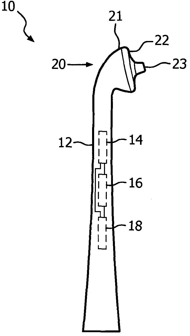
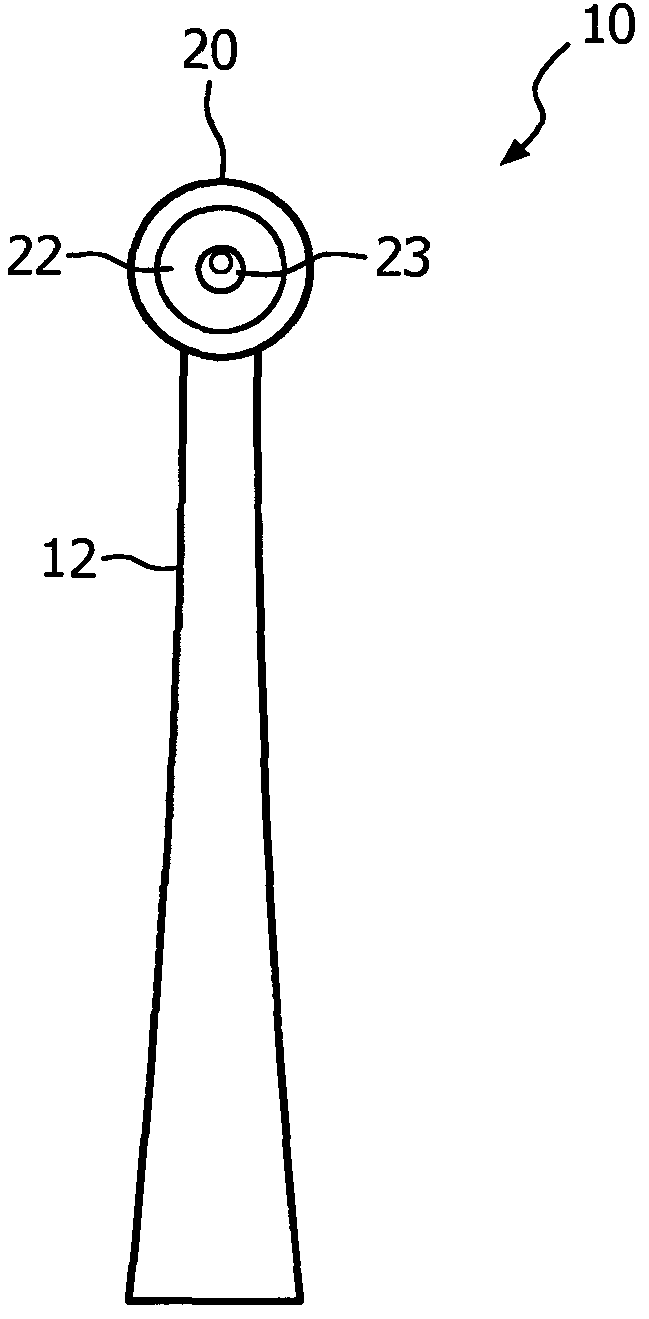
[0011] figure 1 and 2 Overall there is shown a cleaning appliance 10 for teeth which produces a high velocity stream of liquid droplets, such as water, to perform a cleaning function. This device is especially useful when cleaning the interdental area. The appliance 10 generally includes an elongated body portion 12 including a droplet generation system 14, a power assembly 16 for the appliance, and a control assembly 18 for control of the droplet system. exist Figure 8 A variation of this configuration is shown in , where 20A refers to the nozzle assembly and 12A refers to a separate handle portion, where the droplet generation system 14, power assembly 16, and control assembly 18, as well as any other elements required for the operation of the appliance, are located. in the handle section. These parts are not explained in detail, as they can take various conventional forms and configurations. exist figure 1 and 2 In the embodiment, the elongated body portion 12 termi...


PUM


Abstract

The appliance includes an elongated body portion (2) and an assembly (14, 16 18) for producing high velocity water droplets, as well as a nozzle and guidance assembly (20) which includes a base portion (21) and a replaceable tip portion(22). The tip portion is connectable to the base portion by a connection arrangement, such as a weld, an adhesive, or a threaded connection.

Description

technical field [0001] The present invention relates generally to dental appliances for generating high velocity water droplets for cleaning, and more particularly to nozzle assemblies for such appliances. Background technique [0002] US Patent Application 61 / 281,589 discloses a tooth cleaning implement having a main body portion within which are typically located a droplet generation system, a power supply and a control system with an on-off switch for the user. The appliance terminates in an integrated nozzle and guide assembly having a specific tip configuration comprising a central extension member through which high velocity water droplets are output, a central groove portion and an edge ring portion At its highest point it extends above the outer border of the groove portion. [0003] While overall this configuration is suitable for many users, this configuration of the disclosed nozzles does not work well for every user. Additionally, the nozzle assembly should be ...

Claims


Application Information

Patent Timeline
IPC IPC(8): A61C17/02
CPCA61C17/024
Inventor D·德芬鲍格D·埃德沃德
Owner KONINKLIJKE PHILIPS ELECTRONICS NV
Features
  • Generate Ideas
  • Intellectual Property
  • Life Sciences
  • Materials
  • Tech Scout
  • Unparalleled Data Quality
  • Higher Quality Content
  • 60% Fewer Hallucinations
Learn More