
System for correcting thermal displacement of machine tool

A technology of thermal displacement correction and thermal displacement, which is applied in general control systems, control/regulation systems, computer control, etc., and can solve problems that may also occur on the workbench

Inactive Publication Date: 2013-06-12
MITSUBISHI HEAVY IND LTD
View PDF11 Cites 18 Cited by
  • Summary
  • Abstract
  • Description
  • Claims
  • Application Information

AI Technical Summary

Problems solved by technology

[0008] On the other hand, the thermal displacement of the machine tool may occur not only at the mechanical structure such as the spindle or the column with the heat source, but also at the table

Method used


Image

  • System for correcting thermal displacement of machine tool
  • System for correcting thermal displacement of machine tool
  • System for correcting thermal displacement of machine tool

Examples


Embodiment Construction

[0054] Hereinafter, embodiments of the present invention will be described in detail based on the drawings.

[0055]

[0056] based on Figure 1 ~ Figure 3 , the thermal displacement correction system of the machine tool according to Embodiment 1 of the present invention will be described.

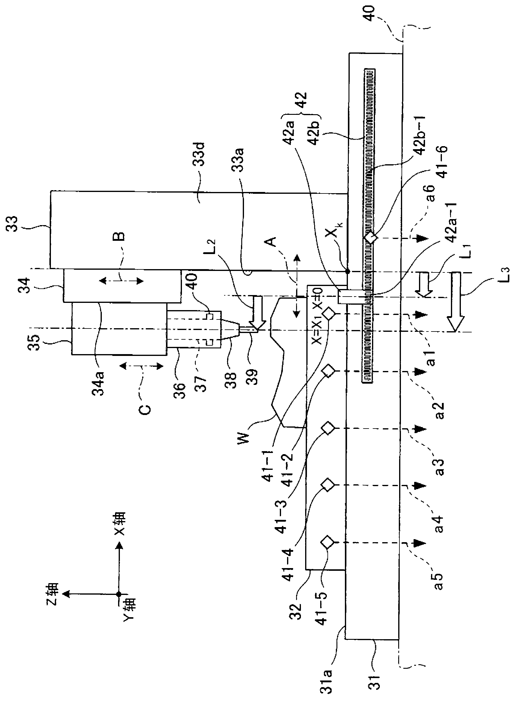
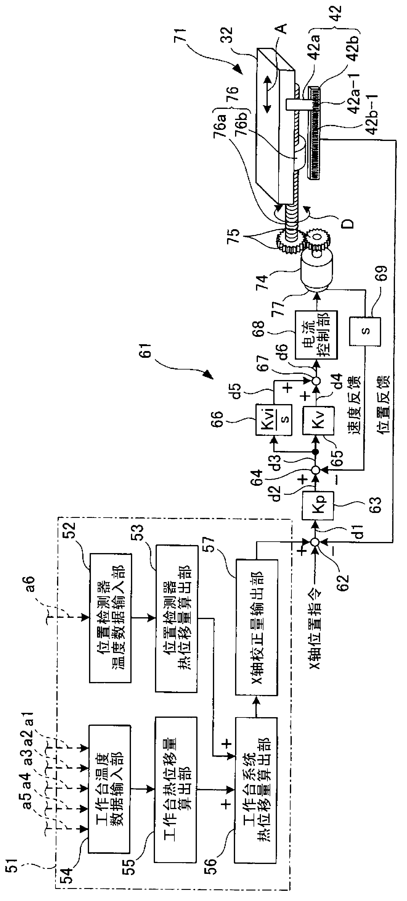
[0057] Such as figure 1 As shown, the machine tool includes: a bed 31, a workbench 32, a door-type column 33, a beam 34, a saddle 35, a ram 36, a built-in spindle 37 rotatably supported on the ram 36, and an attachment 38 The tool 39 and the position detector 42 are attached to the spindle 37 .

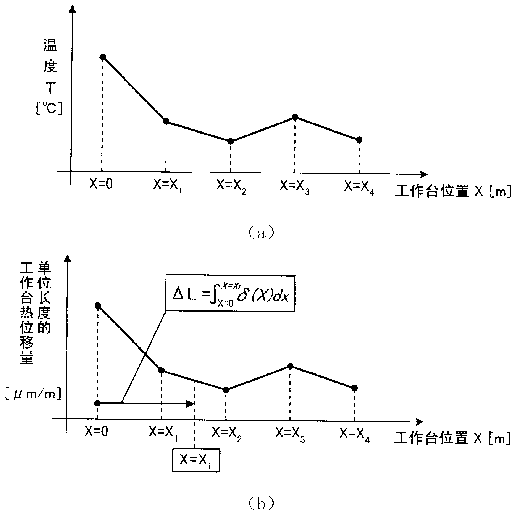
[0058] The bed 31 is arranged on the bed surface 40 . A workbench 32 and a column 33 are provided on the bed 31 , and a workpiece W is placed on the workbench 32 . The workbench 32 can pass the feed mechanism ( figure 1 , the illustration is omitted: figure 2 Reference) linearly moves in the horizontal X-axis direction indicated by arrow A (the front-back direction of the column 33 ). Th...


PUM


Abstract

The purpose of the present invention is to provide a system for correcting thermal displacement of a machine tool, said system being capable of evaluating the amount of thermal displacement with a column front face serving as a reference position, and being capable of performing thermal displacement correction with good precision even when the amount of thermal displacement of a table is not uniform. For this purpose, the system is provided with, for example: a position detector temperature sensor (41-6); table temperature sensors (41-1 to 41-5); and a displacement correction device. The displacement correction device comprises: a temperature data input section for inputting temperature data (a6); a thermal displacement amount calculation section for calculating the amount of thermal displacement of the position detector on the basis of the temperature data (a6); a temperature data input section for inputting temperature data (a1 to a5); a thermal displacement amount calculation section for calculating, on the basis of the temperature data (a1 to a5), the amount of thermal displacement of the table corresponding to a temperature distribution in the X axis direction; a thermal displacement amount calculation section for calculating the amount of thermal displacement of the table system with the column front face serving as the reference position, said calculation being performed on the basis of the amount of thermal displacement of the table and the amount of thermal displacement of the position detector; and an X axis correction amount output section for outputting an X axis correction amount on the basis of the amount of thermal displacement of the table system.

Description

technical field [0001] The invention relates to a thermal displacement correction system of a machine tool. Background technique [0002] In general, in the control system of machine tools, etc., the Figure 12 The shown position information on the machine tool end is detected by the position detector 1 and used as a fully closed-loop feedback control system for position feedback. However, mechanical displacement occurs due to heat sources such as the spindle or servo motor 2 inside the machine tool and changes in external temperature. Therefore, static accuracy such as positioning accuracy of each moving axis or positioning accuracy in a three-dimensional space deteriorates. In addition, mechanical displacement occurs not only due to thermal displacement but also due to deflection or the like due to the weight of the machine. [0003] Further, when using such as Figure 13 When the shown semi-closed-loop feedback control system is used as a control system for a machin...

Claims


Application Information

Patent Timeline
Patent Type & Authority Applications(China)
IPC IPC(8): B23Q15/18B23Q17/00G05B19/404G05D3/12
CPCG05B19/404G05B2219/49206Y10T409/300896B23Q15/18B23Q17/00G05D3/12
Inventor 山本英明
Owner MITSUBISHI HEAVY IND LTD
Learn More