
Air supply device

An air supply device and fan technology, which can be used in hair drying devices, devices for washing hair or scalp, clothing, etc., and can solve problems such as entanglement

Inactive Publication Date: 2013-06-19
PANASONIC CORP
View PDF7 Cites 5 Cited by
  • Summary
  • Abstract
  • Description
  • Claims
  • Application Information

AI Technical Summary

Problems solved by technology

[0006] Here, in the above-mentioned conventional air blower, since the substantially central portion of the second filter is formed in a shape that bulges toward the first filter, the air blower has a structure in which hairs are easily entangled near the fan.

Method used


Image

  • Air supply device
  • Air supply device
  • Air supply device

Examples


no. 1 Embodiment approach ]

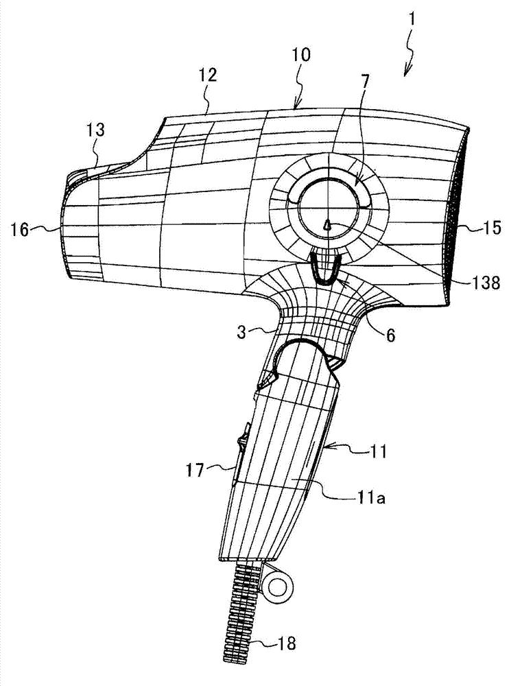
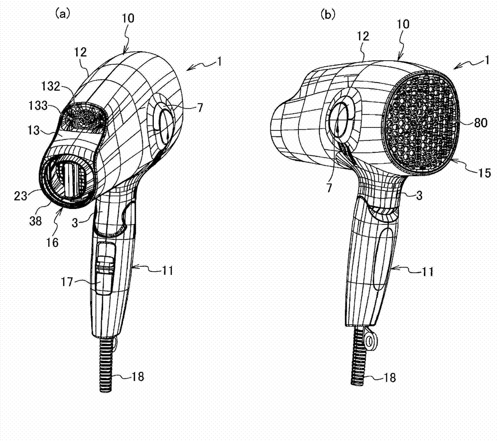
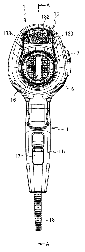
[0026] Figure 1 to Figure 9 It is a figure which shows the air blower of 1st Embodiment of this invention, In this embodiment, the case where this invention is applied to the hair dryer which is an air blower is mentioned.

[0027] Such as figure 1 As shown, the hair dryer 1 has a grip part 11 as a part held by the user and a main body part 10 combined with the grip part 11 in a direction intersecting with the grip part 11. When in use, the grip part 11 It is constituted with the main body 10 to have a substantially T-shape (alphabet T) appearance. The hair dryer 1 has casings (body casing, grip casing) 12 , 11 a as its contour formed by combining a plurality of divided bodies, and a power cord 18 is drawn out from the protruding end of the grip casing 11 a. In addition, on the lower side of the main body portion 10, a grip mounting portion 3 is protrudingly provided, and a connecting portion 19 of the grip mounting portion 3 (refer to Figure 4 ) is connected with a gripp...

no. 2 Embodiment approach ]

[0061] Figure 11 It is a figure which shows the 2nd embodiment of this invention, and will Figure 11 Components that are the same as those in the first embodiment described above are given the same reference numerals, and redundant descriptions will be omitted.

[0062] The main difference between the hair dryer 1 of this embodiment and the above-mentioned first embodiment is that the substantially center portion b of the second filter 90A is bulged toward the fan 26 side. That is, the linear distance L1 along the axial direction between the substantially central portion b of the second filter 90A and the head portion 26a (upstream end a) of the fan 26 is larger than the distance L1 between the outer peripheral portion c and the head portion 26a (upstream end a). a) The linear distance between L3 along the axial direction is short (shorter) for the structure.

[0063] In this way, the second filter 90A of this embodiment adopts the shape of the second filter 90 when the bl...


PUM

PropertyMeasurementUnit
Thicknessaaaaaaaaaa

Abstract

The invention provides an air supply device comprising a first filter (80) disposed on an inlet port (15) of a main body housing (housing) (12); and a second filter (90) disposed between the first filter (80) and a fan (26). The second filter (90) is characterized in that the second filter (90) is disposed on the housing (12), and a linear distance L1 between an approximately central part (b) of the second filter (90) and a head part (26a) of a fan (26) along an axial direction of the housing (12) is smaller than or equal to a linear direction L1 between an peripheral part (c) of the second filter (90) and a head part (26a) of the fan (26) along the axial direction.

Description

technical field [0001] The invention relates to an air supply device. Background technique [0002] As a conventional air blower, for example, Japanese Patent Application Laid-Open No. 2008-307221 discloses that a second filter is arranged between a fan arranged inside the housing and a first filter provided at the suction port of the housing. filter (described as a third filter in Patent Document 1). [0003] In Patent Document 1, a mesh-shaped filter with a mesh width of 300 μm to 650 μm is used as the second filter so that fine dust and hair can be captured without reducing the air volume. [0004] However, the thickness of the hair is 50 μm to 150 μm, and it is difficult to completely prevent the intrusion of the hair into the housing even if the above-mentioned second filter of the prior art is used. [0005] The hair passing through the second filter reaches the fan and is bounced off by the fan, resulting in entanglement of the hairs. If it is in the initial state ...

Claims


Application Information

Patent Timeline
IPC IPC(8): A45D20/10
Inventor 宫田博光西田笃史石川朋哉山根裕二
Owner PANASONIC CORP
Learn More