Adjusting device of hydrostatic module

A technology for regulating equipment and hydrostatic pressure, applied in mechanical equipment, components with teeth, liquid variable capacity machinery, etc., to achieve the effect of linear force transmission

Inactive Publication Date: 2013-06-19
ZF FRIEDRICHSHAFEN AG
View PDF9 Cites 2 Cited by
  • Summary
  • Abstract
  • Description
  • Claims
  • Application Information

AI Technical Summary

Problems solved by technology

Furthermore, radial bores and ball heads must be adequately lubricated and must be protected from intrusive contamination

Method used


Image

  • Adjusting device of hydrostatic module
  • Adjusting device of hydrostatic module
  • Adjusting device of hydrostatic module

Examples


Embodiment Construction

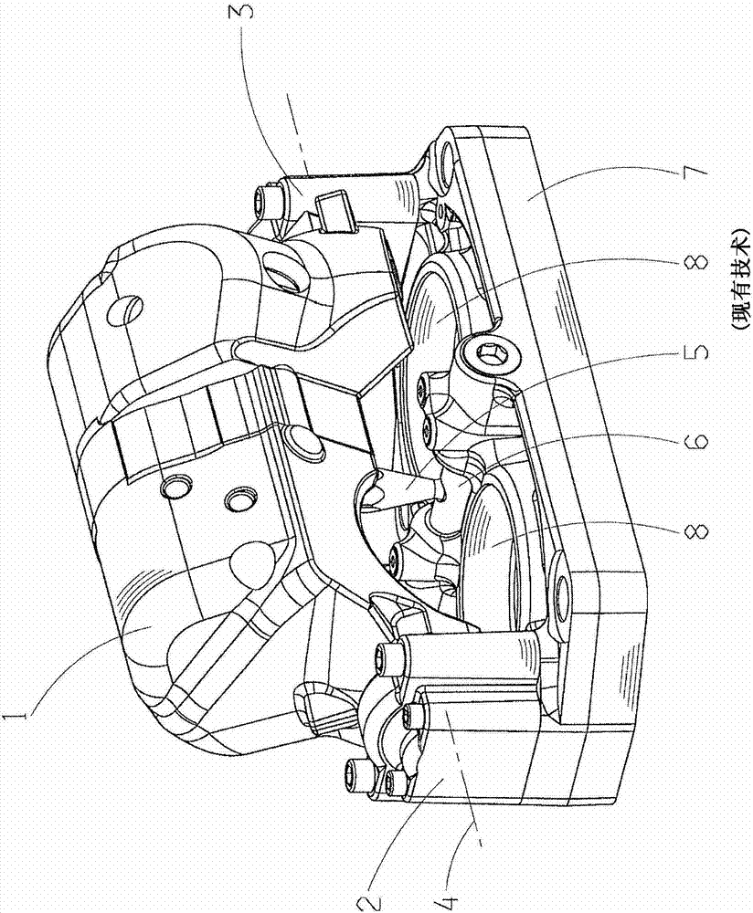
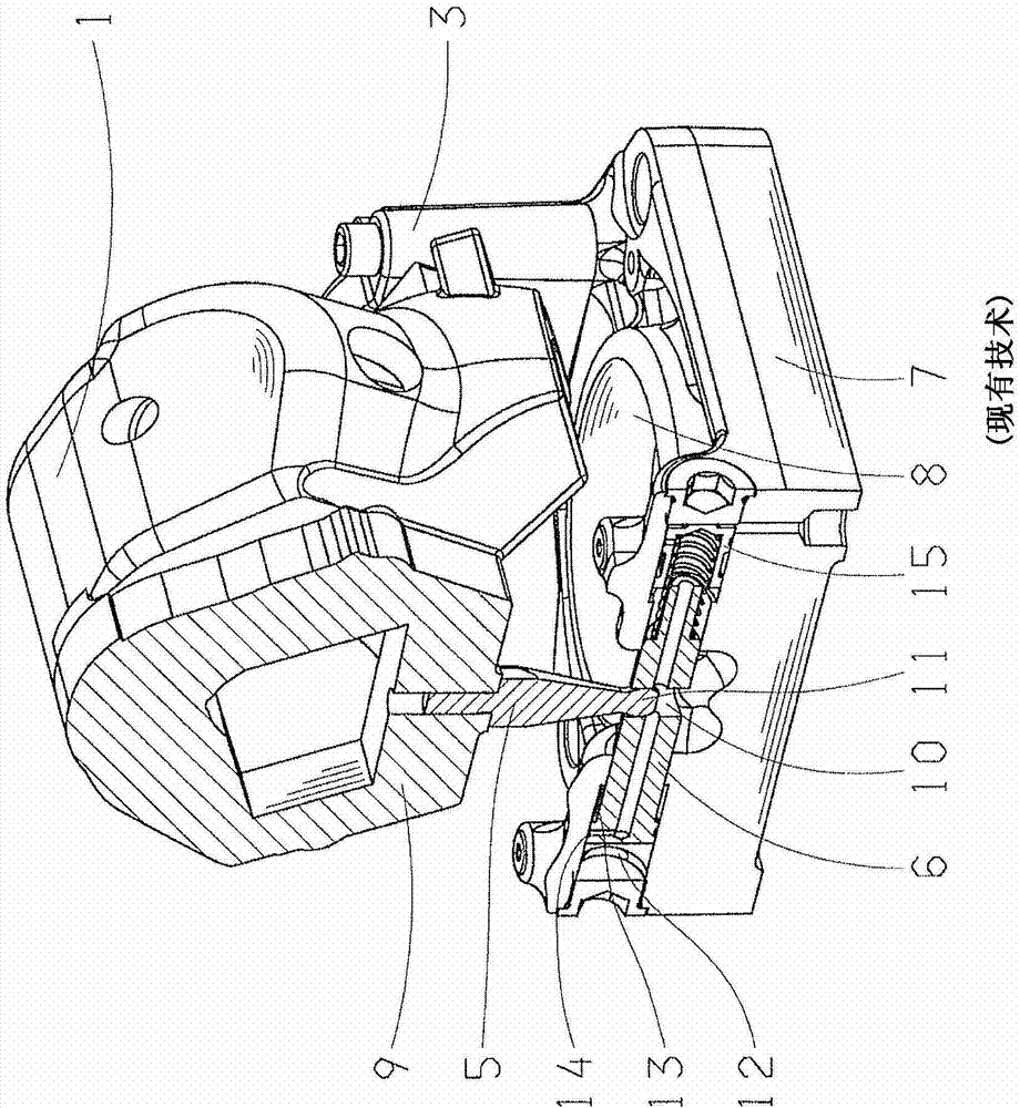
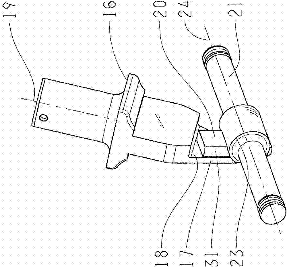
[0026] figure 1 and figure 2 DE 10 2008 002 140 A1 of the same applicant is cited and used to illustrate the structural configuration and function of a hydrostatic module with a yoke 1 pivotable by means of an adjusting piston 6 , while Figure 3 to Figure 5 A different design according to the invention of the coupling device is shown in detail.

[0027] Depend on figure 1 It is evident that the hydrostatic module has a yoke 1 which is mounted rotatably about an axis of rotation 4 via a first mounting device 2 and a second mounting device 3 . Arranged in the yoke 1 are several inclined-axis drives as described in DE 10 2006 025 347 B3. Between the tilt-axis drive is a pivot lever 5 , which engages radially in the adjusting piston 6 . The adjusting piston 6 is accommodated in a bearing plate 7 which carries the bearing device 8 of the tilt-axis drive and is connected to the first bearing device 2 and the second bearing device 3 .

[0028] according to figure 2 , the yok...


PUM


Abstract

An adjusting device of a hydrostatic module comprises at least one axial plunger type machine, of which the emission can be adjusted by pivoting of a yorkpiece. The adjusting device comprises an adjusting cylinder which is provided with an adjusting piston and axially spaced from the rotating axis of the yorkpiece and is perpendicular to the rotating axis of the yorkpiece, a pivoting rod which is in rigid connection with the yorkpiece and substantially faces the rotating axis of the yorkpiece, and a connection device which realizes joint connection between the pivoting rod and the adjusting piston and makes the length compensation of the pivoting rod possible. In order to obtain a stable, simple and cheap structure, the connection device comprises a sliding block which is arranged in a groove which is arranged on the piston in an off-axis manner and is perpendicular to the longitudinal axis of the adjusting piston and allows sliding guide, and a cylindrical pin which is arranged on end piece of the pivoting rod or the sliding block and is perpendicular to the longitudinal axis of the adjusting piston. The cylindrical pin is pivotedly embedded in the sliding block or corresponding drill hole of the end piece of the pivoting rod.

Description

technical field [0001] The invention relates to an adjustment device for a hydrostatic module according to the preamble of claim 1 . Background technique [0002] Known construction types of hydrostatic axial-piston machines are inclined-shaft machines and inclined-disk machines. Such axial piston machines can be used as hydrostatic pumps or hydrostatic motors, respectively, with largely identical construction. In inclined-axis machines, the drive flange is rigidly connected to the associated drive shaft. The piston rods of a plurality of ejector pistons are articulated on the drive flange evenly distributed over the circumference. The ejector pistons are each arranged in one of a plurality of axial cylinder bores which are distributed in the cylinder respectively over the peripheral side. The cylinder is drive-connected, for example via an intermediate cardan shaft, to the drive shaft and is rotatably mounted in the yoke about its axis of rotation, by pivoting the yoke a...

Claims


Application Information

Patent Timeline
Patent Type & Authority Applications(China)
IPC IPC(8): F16H61/433F16H61/423
CPCF04B1/20F04B1/32
Inventor 罗兰·雷坦兹乌多·布雷默
Owner ZF FRIEDRICHSHAFEN AG
Why Eureka
Try Eureka