Supercharge Your Innovation With Domain-Expert AI Agents!

Contactor

A contactor and contact technology, applied in the direction of connection, conductive connection, electrical component connection, etc., can solve the problems of small contact surface and small contact stroke, and achieve the effect of good contact performance

Inactive Publication Date: 2013-06-19
刘永杰
View PDF0 Cites 1 Cited by
  • Summary
  • Abstract
  • Description
  • Claims
  • Application Information

AI Technical Summary

Problems solved by technology

Most of the existing contactors use electric energy as the power source, and there are many disadvantages such as too small contact stroke and small contact surface.

Method used


Image

  • Contactor
  • Contactor
  • Contactor

Examples


Embodiment Construction

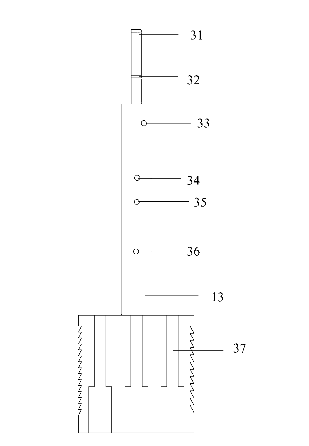
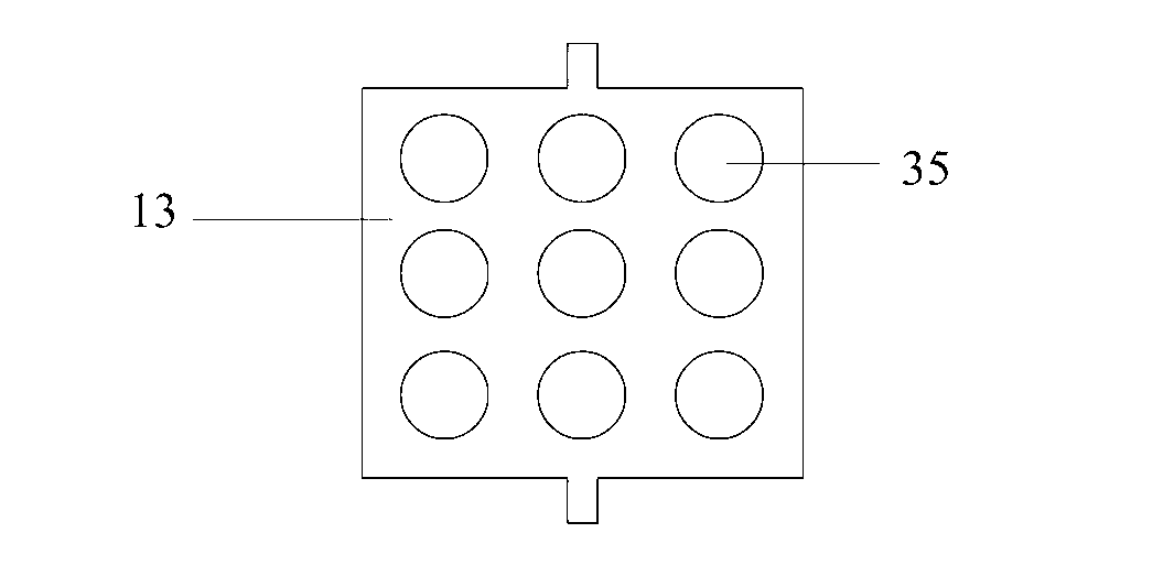
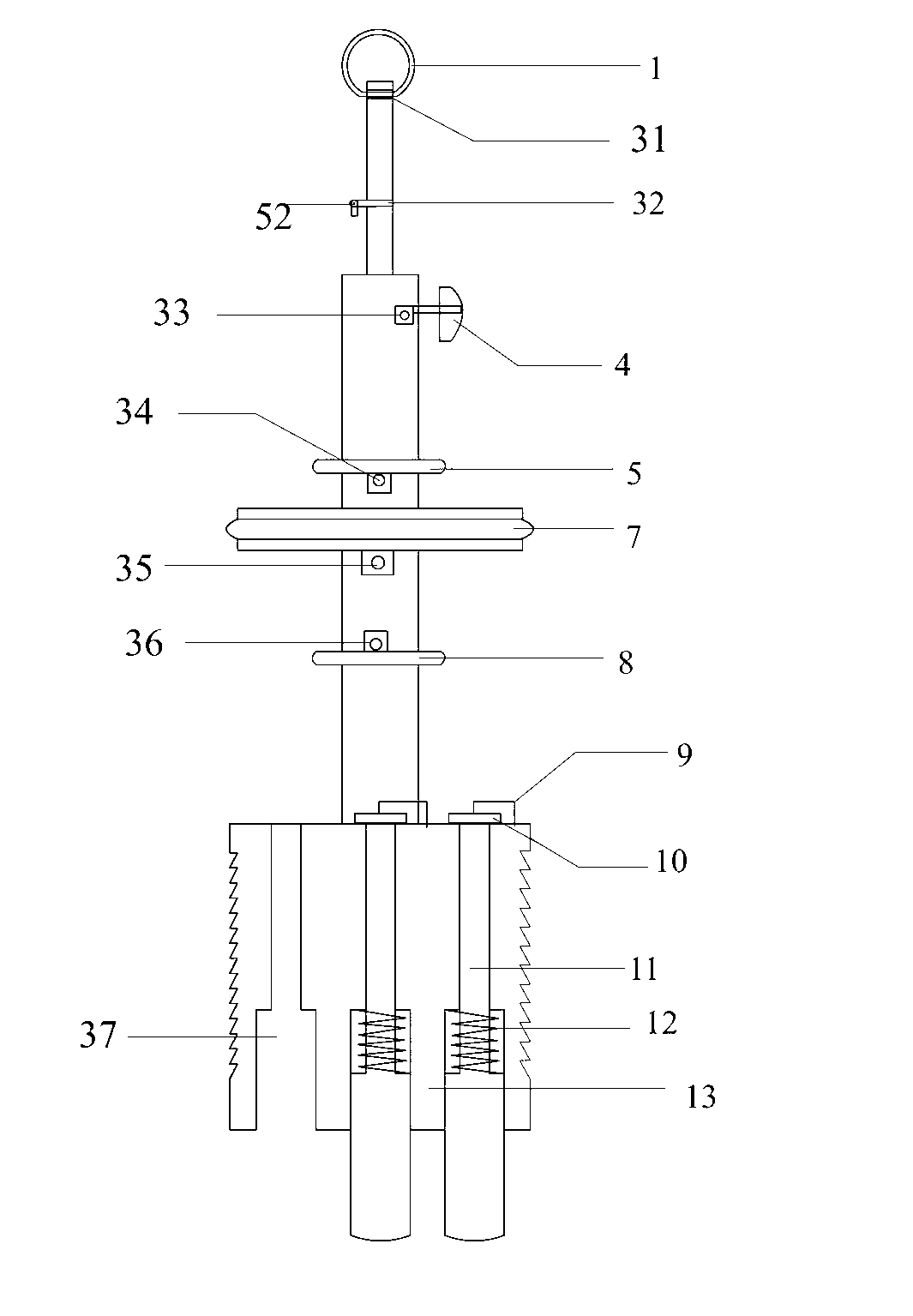
[0015] The present invention is realized like this: as ( figure 1 ), the axis (13) is an integral structure, which can be divided into upper, middle and lower sections. There are pull ring holes (31) and drop-proof holes (32) in the last section. The middle section has a moving contact hole (33), an upper stop hole (34), a piston hole (35), and a lower stop hole (36). There is a contact hole (37) in the next joint. There are helical teeth on both sides of the lower segment. Such as( figure 2 ), the bottom of the axis (13) can be in the shape of a square, a cylinder, etc. Here, a square is taken as an example. A plurality of contact holes (35) are arranged inside, and a plurality of contacts (11) and contact springs (12) can be placed inside. Such as( image 3 ), the pull ring (1) is placed in the pull ring hole (31), and lifting the pull ring (1) can drive the entire main shaft to move upward. Then the anti-fall pin (52) is inserted in the anti-fall hole (32) to lock t...


PUM


Abstract

Disclosed is an air pressure contactor. Under the function of a braking spring (29), a clutch disc (28) is meshed with an axle center (13) and carries out braking to the axle center (13). When compressed air passes through a first braking contraction hole (18) and enters a braking cylinder (23), a barking piston (30) is pushed to move rightwards, the barking piston (30) drives a braking shaft (27) to move rightwards, and the clutch disc (28) is enabled to remove the braking to the axle center (13). The compressed air enters an upper contraction hole (16) of an air cylinder (21), and a piston (7) is pushed to drive the axle center (13) to move downwards. Downward movement of the axle center (13) drives a moving contact (4) to move downwards and be communicated with a lower auxiliary contact (15). The compressed air passes through a lower contraction hole (17) and enters the air cylinder (21), and the piston (7) is pushed to drive the axle center (13) to move upwards. Meanwhile, the axle center (13) drives the moving contact (4) to move upwards and be communicated with an upper auxiliary contact (14) in an auxiliary cylinder (20).

Description

technical field [0001] The invention relates to a contactor, in particular to a large stroke contactor. Background technique [0002] When shorting the track circuit, the two ends of the shorting wire need to be in contact with the rails on both sides respectively. When the catenary is hung with a ground wire, one end of the ground wire must also be in contact with the rail. When setting the protection work of short-circuit track circuit and hanging ground wire, all are to manually bind one end of ground wire and short-circuit wire on the rail. Complicated procedures reduce the work efficiency of staff. Moreover, when the protection is set, the power failure of the vehicle often occurs. Therefore, there is a need for a contactor with a wide contact area, a large stroke and no need for electricity as a power source to be used as a contactor for a safety protection device for a locomotive. At present, there is no contactor that can replace this work on the locomotive. Mos...

Claims


Application Information

Patent Timeline
IPC IPC(8): H01R11/11H01R11/32
Inventor 刘永杰
Owner 刘永杰
Features
  • R&D
  • Intellectual Property
  • Life Sciences
  • Materials
  • Tech Scout
  • Unparalleled Data Quality
  • Higher Quality Content
  • 60% Fewer Hallucinations
Learn More