Power factor correcting device and correcting method thereof

A power factor correction and current correction technology, which is applied in the field of correction, can solve the problems of internal circuit response speed decrease, increase power consumption, increase circuit space, etc., and achieve the effect of improving correction performance and response speed

Active Publication Date: 2015-05-13
ALPHA & OMEGA SEMICON CAYMAN
View PDF12 Cites 0 Cited by
  • Summary
  • Abstract
  • Description
  • Claims
  • Application Information

AI Technical Summary

Problems solved by technology

Since the above-mentioned patent uses an integrator or an integrating capacitor inside or outside the circuit, the response speed of the internal circuit will be greatly reduced. In addition, a switch is required inside the circuit for discharging the integrating capacitor, which will increase the power consumption. And increase the circuit space

Method used


Image

  • Power factor correcting device and correcting method thereof
  • Power factor correcting device and correcting method thereof
  • Power factor correcting device and correcting method thereof

Examples


Embodiment Construction

[0037] The above and other technical features and advantages of the present invention will be described in more detail below in conjunction with the accompanying drawings.

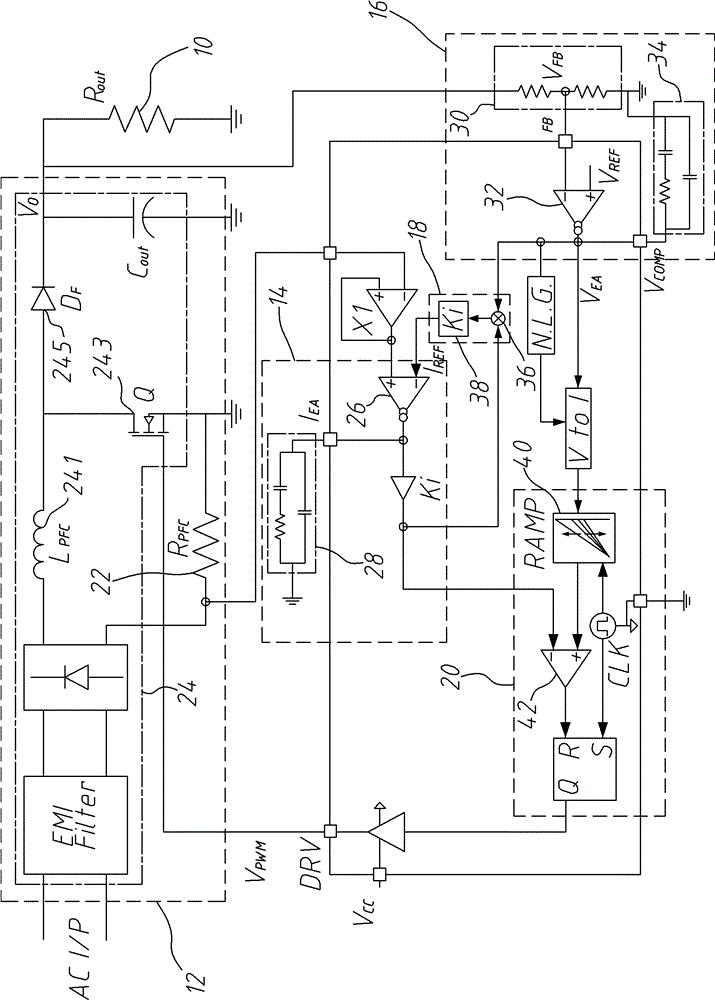
[0038] see figure 1 . The power factor correction device of the present invention is connected to a load 10, and includes a power stage circuit 12, connected to the load 10, and receives an AC voltage V AC and a pulse width modulated signal V PWM , to modulate the signal V according to the pulse width PWM Convert AC voltage V AC is an input current I AC , and output it to the load 10, so that an output voltage V is generated on the load 10 o , and sample the input current I AC , as a correction current I sen output. The power stage circuit 12 is connected to a current compensation circuit 14 and a voltage compensation circuit 16 . The current compensation circuit 14 receives the correction current I sen and a reference current signal I ref , and compare the two to generate a compensation current...


PUM


Abstract

The invention discloses a power factor correcting device and a correcting method of a power factor. The power factor correcting device and the correcting method of the power factor keep that an input current is in a simple sinusoidal alternating current form and keeps the input current shares the same phase with an input alternating voltage. An alternating voltage is converted into a full-wave rectification form through a full-bridge rectifier, and is converted into a direct current output voltage through an inducer, a power transistor and a power diode. A current compensating circuit and a voltage compensating circuit respectively generate a compensating current signal and a compensating voltage signal after respectively comparing a correcting current and an output voltage respectively with a reference signal and a reference voltage, and an updated pulse width modulation signal is generated according to the compensating current signal and the compensating voltage signal. The reference current signal is obtained through multiplying the compensating current signal by the compensating voltage signal through a multiplication gainer, so that the input current can be corrected without the needs of sampling an input voltage according to the technology, and response speed of an internal circuit is improved.

Description

technical field [0001] The present invention relates to a correction technology, in particular to a power factor correction device and a correction method thereof. Background technique [0002] Today's power supply industry's pursuit of high-quality power supply and demand has always been the goal that countries around the world want to achieve. However, building a large number of power plants is not the only way to solve the problem. Power factor (power factor) or efficiency can effectively solve the problem. The main function of the power factor corrector is to make the phase of the input voltage of the electrical product and the input current the same, which means that the load of the electrical product is similar to a resistive load, and effectively reduces the harmonic distortion of the input current ( current harmonic distortion) to achieve high power factor of power supply. [0003] A general power factor correction device not only needs a pulse width modulation sig...

Claims


Application Information

Patent Timeline
Patent Type & Authority Patents(China)
IPC IPC(8): H02M1/42
CPCY02B70/10
Inventor 古忠平黄伟骐
Owner ALPHA & OMEGA SEMICON CAYMAN
Why Eureka
Try Eureka