Eureka AIR delivers breakthrough ideas for toughest innovation challenges, trusted by R&D personnel around the world.

A method and device for channel estimation

A channel estimation and channel technology, applied in the field of channel estimation, can solve the problems of channel tap energy leakage and inaccurate channel estimation, and achieve the effects of accurate results, accurate filtering coefficients, and accurate frequency domain filtering.

Active Publication Date: 2016-02-03
LEADCORE TECH
View PDF6 Cites 0 Cited by
  • Summary
  • Abstract
  • Description
  • Claims
  • Application Information

AI Technical Summary

Problems solved by technology

[0022] In order to solve the problem in the prior art that the channel taps are not necessarily at integer multiple sampling points, which will cause energy leakage of the channel taps, resulting in inaccurate channel estimation, an embodiment of the present invention provides a method and device for channel estimation

Method used


Image

  • A method and device for channel estimation
  • A method and device for channel estimation
  • A method and device for channel estimation

Examples


Embodiment 1

[0044] Before introducing the embodiment of the present invention, first introduce the new channel delay power spectrum proposed by the embodiment of the present invention,

[0045] θ ( τ m ) = 1 / L 0 τ m ∈ [ - τ leak , L 0 - τ leak ] 0 otherwise ...

Embodiment 2

[0054] An embodiment of the present invention provides a channel estimation method, such as Figure 5 shown, including:

[0055] S1. Perform initial channel estimation LS according to the reference signal RS, and estimate the frequency domain response of the channel at the reference signal

[0056] S2. Calculate the frequency domain response The amount of phase rotation θ is required, where the calculation method of the amount of phase rotation θ is:

[0057] θ = τ A + τ max 2 - τ leak ,

[0058] In the above formula, τ leak is the leakage value of the channel tap caused by non-integer multiple sampling, which is related to the frequency of sampling, and the specific value is obtained by simulation; τ A is the sampling point received in advance; τ max is the estimated value of th...

Embodiment 3

[0073] The embodiment of the present invention also provides a channel estimation device, such as Figure 8 shown, including:

[0074] The initial channel estimation unit 801 is configured to perform initial channel estimation on the reference signal, and estimate the frequency domain response of the channel at the reference signal

[0075] Phase rotation unit 803, used to calculate the The amount θ that needs to be phase rotated, and the Perform theta phase rotation;

[0076] An interpolation filtering unit 805, configured to, according to the correlation between each subcarrier, perform the θ phase rotation on the Perform interpolation and filtering;

[0077] The phase derotation unit 807 is configured to perform θ phase derotation on the interpolated and filtered values ​​to obtain the channel estimation value of the reference signal.

[0078] The channel estimation device provided by the embodiment of the present invention considers the influence of the energy le...


PUM


Abstract

An embodiment of the present invention provides a method and device for channel estimation, wherein the method includes performing initial channel estimation on a reference signal, estimating the frequency domain response of the channel at the reference signal, and calculating the amount θ that needs to be phase rotated, and performing θ phase rotation; according to the correlation between each subcarrier, interpolating and filtering the θ phase rotation; performing θ phase derotation on the interpolated and filtered values ​​to obtain the The channel estimate of the reference signal. The method and device provided by the embodiments of the present invention consider the influence of the energy leakage of channel taps caused by non-integer multiple sampling on the frequency domain filtering when performing channel estimation, so that the frequency domain filtering is more accurate, and at the same time, the calculation When filtering coefficients, the influence of early reception is considered to make the filtering coefficients more accurate; this makes the result of estimating the reference signal more accurate.

Description

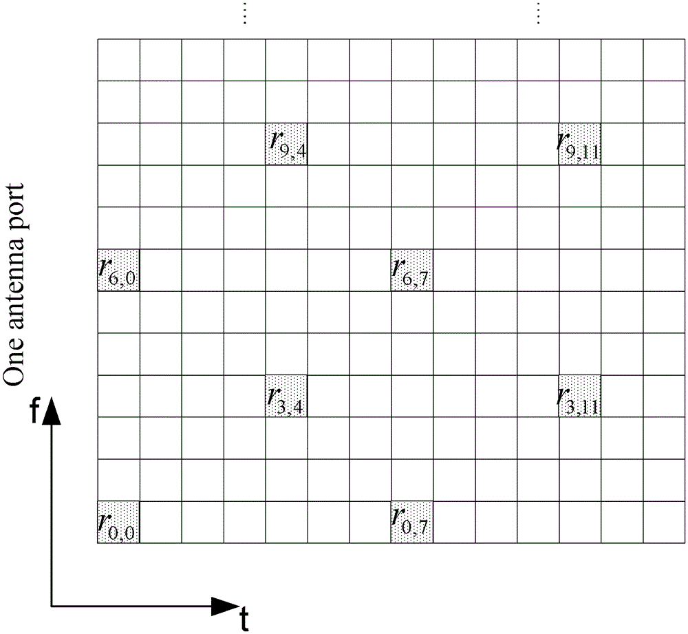
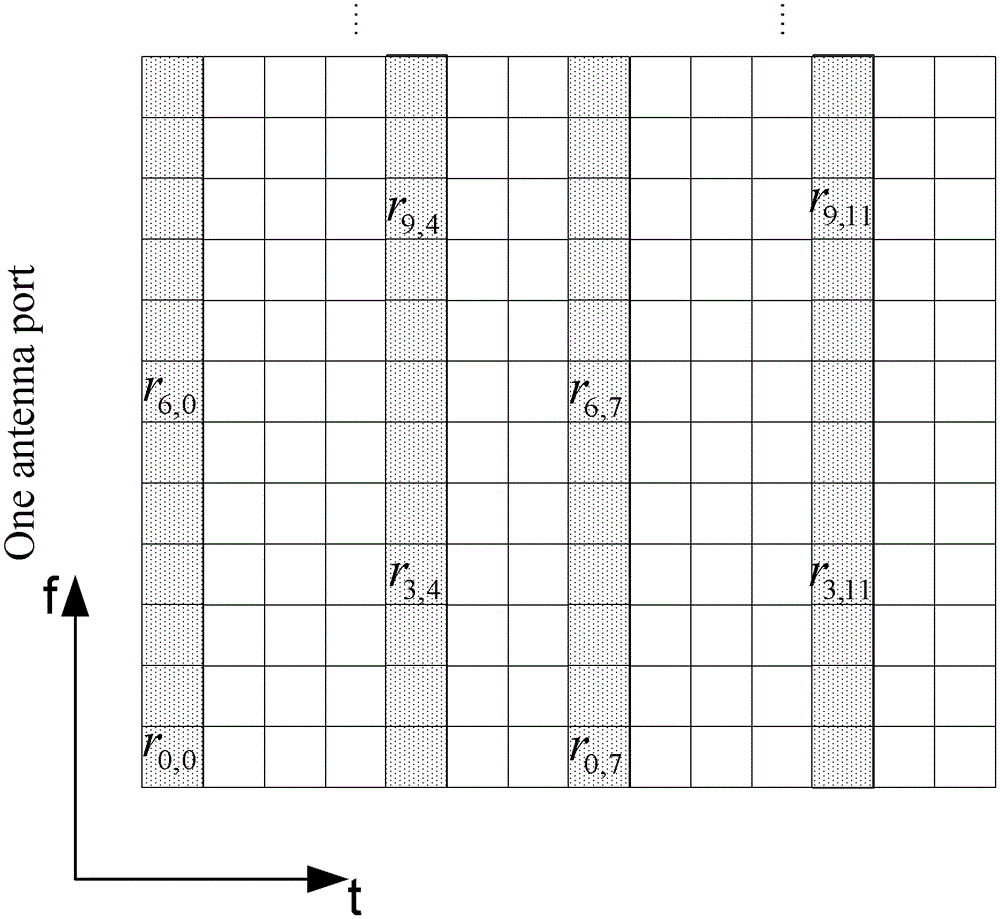
technical field [0001] The present invention relates to the communication field, in particular to a channel estimation method and device. Background technique [0002] In an Orthogonal Frequency Division Multiplexing (Orthogonal Frequency Division Multiplexing, OFDM) system, a Reference Signal (RS) discretely inserted in the time-frequency domain is usually used for channel estimation. The typical one is to use two-dimensional linear minimum mean square error (LinearMinimumMeanSquareError, LMMSE) channel estimation, that is, after initial channel estimation at RS, minimum mean square error (MinimumMeanSquareError, MMSE) filtering is performed in the frequency domain and time domain respectively. , interpolation to obtain the channel estimate at the data position. [0003] Taking the Long Term Evolution (LTE) system as an example, the distribution of reference signals in the time-frequency domain is as follows: figure 1 As shown in , where the square with shaded background ...

Claims


Application Information

Patent Timeline
Patent Type & Authority Patents(China)
IPC IPC(8): H04L25/02H04L27/26
Inventor 康国庆廖伟邓瑞楠
Owner LEADCORE TECH
Why Eureka
Eureka Blog
Learn More