Multi-directional hydraulic extrusion press for semi-solid metal forming

A semi-solid metal, multi-directional extrusion technology, which is applied in the field of multi-directional extrusion hydraulic presses for semi-solid metal forming, can solve the problems of non-adjustable hydraulic cylinders, inconvenient mold loading, and unfavorable adjustments, so as to facilitate installation and fixation , to ensure the effect, to overcome the effect of uneven force

Inactive Publication Date: 2013-06-26
XI AN JIAOTONG UNIV
View PDF4 Cites 8 Cited by
  • Summary
  • Abstract
  • Description
  • Claims
  • Application Information

AI Technical Summary

Problems solved by technology

[0003] The disadvantage of the above-mentioned multi-directional extrusion hydraulic press is first of all that the multi-directional extrusion hydraulic press that only fixes a piston hydraulic cylinder in the front, rear or left and right directions on the upper surface of the lower crossbeam can only be loaded in four directions, which cannot meet the complex requirements. Die-parting in six directions of the part cannot realize the pressure forming of the part in six directions; secondly, for the multi-directional extrusion forming hydraulic machine that can realize loading in six directions, the upper surface of the lower beam is fixed in four directions, front, rear, left, and right respectively. A piston type hydraulic cylinder, the position of the hydraulic cylinder in the vertical direction cannot be adjusted, which is not convenient for loading the mold, and it is also not conducive to adjusting the four directions of the front, rear, left, and right sides of the upper surface of the lower crossbeam when using molds of different sizes. The loading position of the multi-directional extrusion molding hydraulic press that can only be loaded in four directions also has the above disadvantages
Such equipment obviously cannot meet the mass production and manufacturing of various types and specifications of high-precision parts in modern industry

Method used


Image

  • Multi-directional hydraulic extrusion press for semi-solid metal forming
  • Multi-directional hydraulic extrusion press for semi-solid metal forming
  • Multi-directional hydraulic extrusion press for semi-solid metal forming

Examples


Embodiment Construction

[0013] The present invention will be further described in detail below in conjunction with the accompanying drawings.

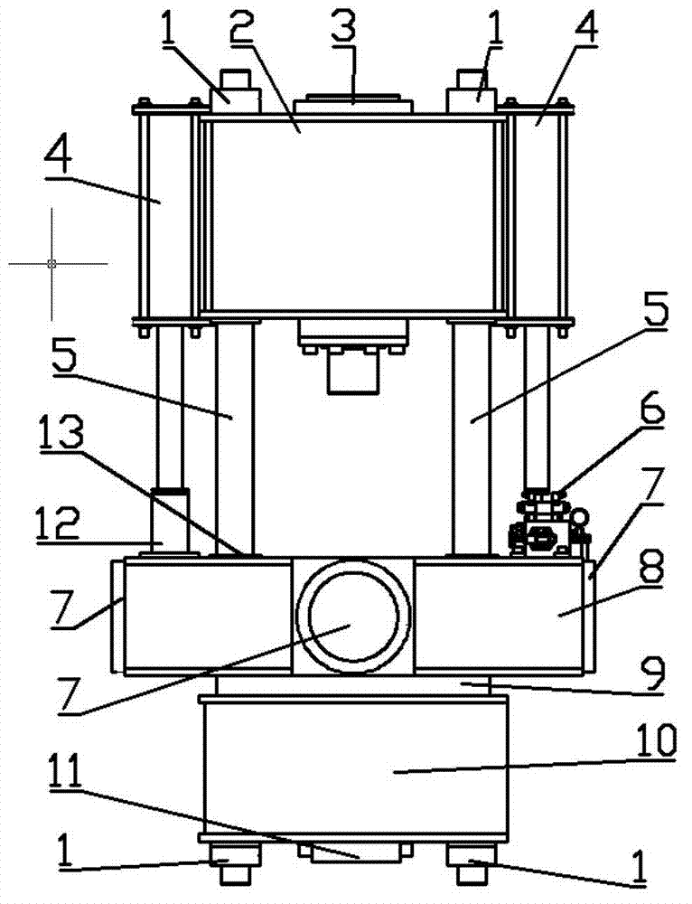
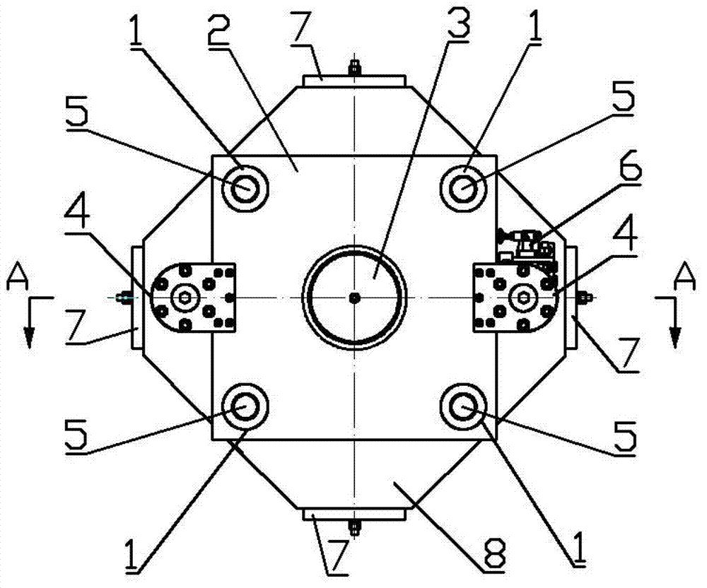
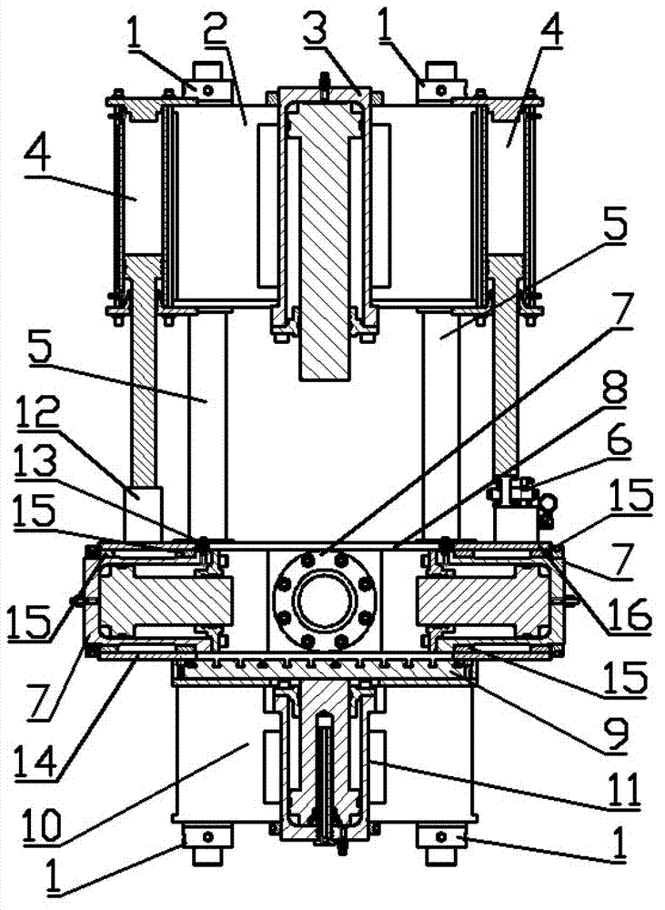
[0014] refer to figure 1 , figure 2 and image 3 , a multi-directional extrusion hydraulic press for semi-solid metal forming, comprising a cuboid-shaped upper beam 2, a cuboid-shaped lower beam 10 and a moving beam 8, a through hole is opened at the center of the upper beam 2 and the upper beam piston cylinder is installed 3. Open a through hole at the center of the lower beam 10 and install the inner piston cylinder 11 of the lower beam. There are four through holes at the four corners of the upper beam 2. Four through holes are opened at the four corners of the lower beam 10. holes, the tops of the four locking rods 5 respectively pass through the four through holes at the four corners of the upper beam 2, the lower surface of the upper beam 2 contacts and presses the shoulders on the four locking rods 5, and the four The tail ends of the locking rods ...


PUM


Abstract

The invention discloses a multi-directional hydraulic extrusion press for semi-solid metal forming. The multi-directional hydraulic extrusion press comprises a moving transverse beam, wherein the moving transverse beam is positioned between an upper transverse beam and a lower transverse beam and is put on a working table connected with the top part of the lower transverse beam; the moving transverse beam is of an octagon symmetric welded frame structure; an oil port on an oil supply valve piece of the moving transverse beam is connected with the oil inlets and oil outlets of four piston cylinders inside the moving transverse beam; an oil return path of an oil return path block is also connected with the oil supply valve piece of the moving transverse beam; piston rods of two side surface lifting piston cylinders are respectively connected with the upper surfaces of the oil supply valve piece and the oil return path block of the moving transverse beam; the front end rear end covers of the two side surface lifting piston cylinders are respectively fixed on the upper transverse beam; and the moving transverse beam vertically moves along the vertical direction of the moving transverse beam. the installation and the fixation of a fixed die and the working table on the lower transverse beam and the installation and the fixation of the piston cylinders inside the moving transverse beam are facilitated; and the multi-directional hydraulic extrusion press has the advantages that a die can be split and pressed in multiple directions, the forming forces of a part are relatively uniform, the moving transverse beam can vertically move along the vertical direction, and the like.

Description

technical field [0001] The invention belongs to the technical field of precision forming equipment for complex parts, and in particular relates to a multi-directional extrusion hydraulic press for semi-solid metal forming. Background technique [0002] The multi-directional extrusion hydraulic presses currently available in the market are mainly composed of three parts: the upper beam, the tie rod, and the lower beam. A through hole is opened in the center of the upper beam and a piston hydraulic cylinder or plunger hydraulic cylinder is installed. There are four upper beams. Four through holes are opened at the corners to connect with the tie rods, and a piston hydraulic cylinder is respectively fixed on the upper surface of the lower crossbeam in four directions: front, rear, left and right; One piston hydraulic cylinder is respectively fixed, and a through hole is opened in the center of the lower beam to install a piston hydraulic cylinder or a plunger hydraulic cylinder...

Claims


Application Information

Patent Timeline
Patent Type & Authority Applications(China)
IPC IPC(8): B21C23/21
Inventor 赵升吨张晨阳郭桐韩晓兰刘辰
Owner XI AN JIAOTONG UNIV
Why Eureka
Try Eureka