Steel bar binding space distance identification device

A marking device and steel bar binding technology, which is applied in the direction of construction, building structure, and building material processing, can solve the problems of low construction efficiency and inconvenient operation, and achieve the effects of improved work efficiency, clear marking, and high efficiency

Active Publication Date: 2015-06-10
SINOHYDRO BUREAU 14 CO LTD
View PDF6 Cites 0 Cited by
  • Summary
  • Abstract
  • Description
  • Claims
  • Application Information

AI Technical Summary

Problems solved by technology

The process is inconvenient to operate and the construction efficiency is low

Method used


Image

  • Steel bar binding space distance identification device
  • Steel bar binding space distance identification device
  • Steel bar binding space distance identification device

Examples


Embodiment Construction

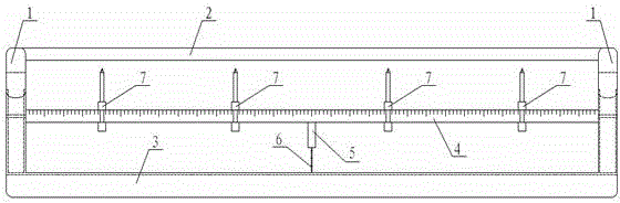
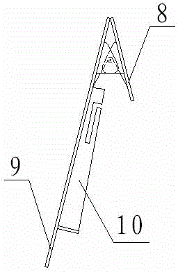
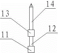
[0015] Such as figure 1 As shown, the device for identifying the spacing between steel bars in reinforced concrete construction of the present invention is composed of two positioning clips 1, upper connecting piece 2, lower connecting piece 3, ruler 4, and vernier pen 7. The ruler is between the upper connecting piece and the lower connecting piece. Two positioning clips are arranged at the two ends of the scale, upper connecting piece and lower connecting piece. The heads of the short tail clips 8 of the two positioning clips are connected to the lower connector through super glue, and the tails of the long tail clips 9 of the two positioning clips pass The super glue is connected with the upper connecting piece, and the ruler is equipped with multiple vernier pens 7.

[0016] The long tail clip piece, the short tail clip piece and the upper and lower connecting pieces of the positioning clip have a thickness of 4 mm, and the materials are all transparent PVC plastic.

[0017] A ...


PUM


Abstract

The invention provides a steel bar binding space distance identification device which comprises two locating clips, an upper connecting piece, a lower connecting piece, a scaleplate and vernier pens. The scaleplate is arranged between the upper connecting piece and the lower connecting piece. The two locating clips are arranged at two ends of the scaleplate, the upper connecting piece and the lower connecting piece. Short tail clip head portions of the two locating clips are connected with the lower connecting piece. Long tail clip tail portions of the two locating clips are connected with the upper connecting piece. The scaleplate is provided with a plurality of vernier pens. The steel bar binding space distance identification device is convenient to operate and high in efficiency. A conventional steel bar binding space distance line-drawing identification needs two persons for matching operation, and when the steel bar binding space distance identification device is used for steel bar binding space distance line-drawing identification, only one person is needed. When the steel bar binding space distance identification device is used for steel bar binding space distance line-drawing identification, working efficiency can be improved by 8-10 times.

Description

Technical field [0001] The invention relates to the technical field of reinforced concrete in civil engineering, in particular to a device for identifying the spacing between steel bars in reinforced concrete construction. Background technique [0002] At present, the steel bar tying process in civil engineering usually firstly uses steel tape measure and stone pen to mark the spacing of the main bars, distribution bars, and stirrups on the erecting bars and the stressed main bars, and then the steel bars are bound. The process is inconvenient to operate and the construction efficiency is low. Summary of the invention [0003] The purpose of the present invention is to overcome the shortcomings of the steel bar spacing identification in the existing steel bar binding process, and provide a steel bar binding spacing identification device with reasonable design, convenient construction and improved economic benefits. [0004] The technical scheme of the present invention is: [0005] ...

Claims


Application Information

Patent Timeline
Patent Type & Authority Patents(China)
IPC IPC(8): E04G21/12
Inventor 刘六艺郭振华王来所缪买和李强安一王晓莉赵国庆郑顺生杨泽恒赵青黎晓开陈香荣杨睿李小庆丁少红钱春留王康陈广杨凯杨浪
Owner SINOHYDRO BUREAU 14 CO LTD
Why Eureka
Try Eureka