
Adjusting ring device for measuring revolution and speed of rotary shaft

A technology of adjusting ring and rotating shaft, applied in the field of measurement, can solve the problems of wasting equipment disassembly, re-installation and debugging time, affecting production, etc., and achieves the effects of stable work, convenient disassembly and installation, and high measurement accuracy

Active Publication Date: 2013-06-26
江西凯润达精密仪器有限公司
View PDF5 Cites 0 Cited by
  • Summary
  • Abstract
  • Description
  • Claims
  • Application Information

AI Technical Summary

Problems solved by technology

[0005] Due to the rotation characteristics of the rotating shaft, it is impossible to measure the rotation speed and speed of the rotating shaft by means of conventional wire transmission signals. The existing method is to disassemble the mechanical equipment and put the measuring device into the rotating shaft to complete the measurement requirements.
This method wastes a lot of equipment dismantling, reinstallation and debugging time, and affects production. Once the measuring device is damaged, the process of equipment disassembly, reinstallation and debugging must be repeated, and this method is not suitable for the rotating shaft of non-detachable equipment. Measurement

Method used


Image

  • Adjusting ring device for measuring revolution and speed of rotary shaft
  • Adjusting ring device for measuring revolution and speed of rotary shaft
  • Adjusting ring device for measuring revolution and speed of rotary shaft

Examples


Embodiment Construction

[0038] In order to express the present invention more clearly, the present invention will be further described below in conjunction with the accompanying drawings.

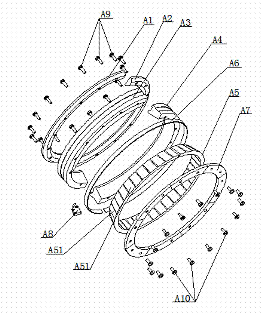
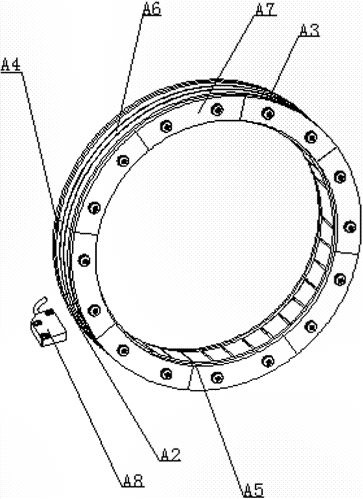
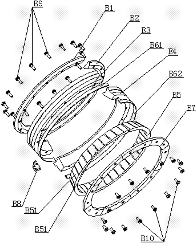
[0039] see Figure 1-2 , the present invention provides the first embodiment of the device with an adjusting ring for measuring the rotation number and rotational speed of the rotating shaft, including the first positioning half ring A1, the second positioning half ring A2, the first intermediate half ring A3, the first positioning half ring Two intermediate half-rings A4, magnetic tape ring A6, compression end plate A7, adjusting ring A5 that can rotate with the rotating shaft and the magnetic sensor A8 for the magnetic signal on the induction tape ring A6; The first positioning half-ring A1 and The second positioning half ring A2 is connected to form a positioning ring, the first middle half ring A3 is connected to the second middle half ring A4 to form a middle ring, the adjustment ring A5 is nested on the inne...


PUM


Abstract

The invention discloses an adjusting ring device for measuring revolution and speed of a rotary shaft. The adjusting ring device comprises a first positioning half ring, a second positioning half ring, a first middle half ring, a second middle half ring, a magnetic tape ring, a compressing end plate, an adjusting ring capable of rotating with the rotary shaft, and a magnetic sensor for sensing magnetic signals on the magnetic tape ring. The first positioning half ring and the second positioning half ring are connected to form a positioning ring. The first middle half ring and the second middle half ring are connected to form a middle ring. The outer wall of the adjusting ring is attached to the inner wall of the middle ring. The magnetic tape ring is adhered to the outer periphery of the middle ring. The positioning ring and the compressing end plate are respectively fixedly connected to the middle ring. The adjusting ring device is applicable to rotary shafts not removable. The problem that the measuring device cannot be nested in or can only be mounted by demounting is solved. The adjusting ring device has the advantages of simplicity in operation, convenience in demounting and mounting, stability in operation, high measuring precision and the like.

Description

[0001] technical field [0002] The invention relates to the field of measurement technology, in particular to a device with an adjustment ring for measuring the rotation number and rotation speed of a rotating shaft. [0003] Background technique [0004] In research fields such as vehicles, manufacturing, and science, it is often necessary to measure various revolutions and rotational speeds in installed equipment to know the operating conditions of the rotating shaft. Especially in large-scale mechanical production equipment, due to the heavy workload and long working hours of each rotating shaft in the equipment, it is necessary to obtain the number of revolutions and speeds of each rotating shaft in the mechanical equipment in real time during operation, and based on these two parameters Monitor the safety performance of mechanical equipment in real time, prevent the failure of mechanical equipment without knowing it, and eliminate potential safety hazards during the o...

Claims


Application Information

Patent Timeline
Patent Type & Authority Applications(China)
IPC IPC(8): G01P3/44
Inventor 腾飏
Owner 江西凯润达精密仪器有限公司
Learn More