Spindle motor

A spindle motor and bearing technology, which is applied in the direction of electrical components, electromechanical devices, electric components, etc., can solve the problems of shortened life of the spindle motor

Inactive Publication Date: 2013-06-26
SAMSUNG ELECTRO MECHANICS CO LTD
View PDF5 Cites 0 Cited by
  • Summary
  • Abstract
  • Description
  • Claims
  • Application Information

AI Technical Summary

Problems solved by technology

[0009] Therefore, the present invention will solve the problem that the life of the spindle motor is shortened due to the vibration phenomenon of the rotor caused by the clearance in the shaft system

Method used


Image

  • Spindle motor
  • Spindle motor
  • Spindle motor

Examples


Embodiment Construction

[0038] The above and other objects, features and advantages of the present invention will be more clearly understood through the following detailed description in conjunction with the accompanying drawings. In the description of the present invention, when a detailed description of related known performance or structure would obscure the gist of the present invention, the detailed description of the known technology will be omitted.

[0039] Hereinafter, preferred embodiments of the present invention will be described in detail with reference to the accompanying drawings.

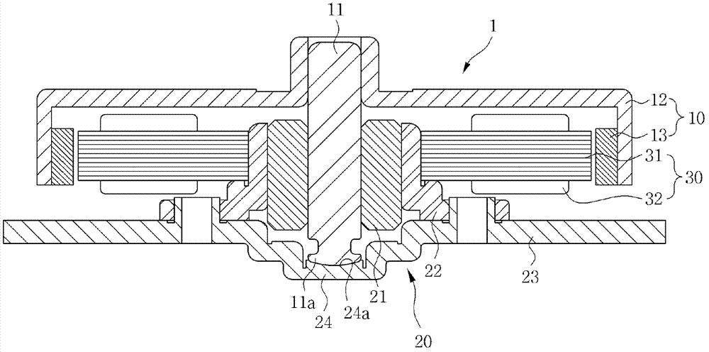
[0040] Such as figure 1 As shown, the spindle motor 1 according to the preferred embodiment of the present invention is composed of a shaft 11, a stator 20, an armature 30, a rotor 10 and a thrust portion 24, the stator 20 includes a bearing 21 to rotatably support the shaft 11, and the armature 30 includes an iron core disposed on the stator 20, and the rotor 10 is installed on an upper portion of the sha...


PUM


Abstract

Disclosed herein is a spindle motor. In the spindle motor according to the present invention, a thrust part is disposed at a lower portion of a shaft, and a support part surface-contacting a lower end of the shaft is formed at the thrust part so as to have a round shape, thereby making it possible to easily prevent a wobble phenomenon of a rotor due to a gap in a shaft system. In addition, a guide part is formed to be protruded at the thrust part to lock the shaft including a narrow part formed therein, thereby making it possible to easily prevent floating of the rotor.

Description

[0001] Cross References to Related Applications [0002] This application claims the priority of Korean Patent Application No. 10-2011-0140301 entitled "Spindle Motor" filed on December 22, 2011, the entire contents of which are hereby incorporated by reference Incorporated into this application in its entirety. technical field [0003] The invention relates to a spindle motor. Background technique [0004] Since the predetermined contact portion is maintained with the bearing when the shaft rotates, the spindle motor can easily maintain the rotation characteristics. Therefore, the spindle motor is widely used as a device for driving a recording medium (recording medium) that requires high-speed rotation, such as a hard disk drive (HDD), an optical disk drive (ODD), and the like. [0005] The spindle motor mechanism becomes to include an armature, a rotor including a main magnet that generates an electromagnetic force between the armature and the main magnet, and a stator ...

Claims


Application Information

Patent Timeline
Patent Type & Authority Applications(China)
IPC IPC(8): H02K21/14H02K5/16
CPCH02K5/1675H02K2205/03G11B19/2009
Inventor 朴玧映崔烈刘永仙
Owner SAMSUNG ELECTRO MECHANICS CO LTD
Why Eureka
Try Eureka