Switching Power Supplies for Low Input Current Ripple

A switching power supply and current ripple technology, applied in the direction of output power conversion devices, electrical components, etc., can solve the problem that the dynamic performance of the circuit is difficult to meet the requirements, and achieve the effect of simple structure, flexible design and adjustment, and strong practicability.

Active Publication Date: 2017-11-03
HARBIN INST OF TECH SHENZHEN GRADUATE SCHOOL
View PDF5 Cites 0 Cited by
  • Summary
  • Abstract
  • Description
  • Claims
  • Application Information

AI Technical Summary

Problems solved by technology

However, after the steady-state performance is guaranteed, the dynamic performance of the circuit is often difficult to meet the requirements.

Method used


Image

  • Switching Power Supplies for Low Input Current Ripple
  • Switching Power Supplies for Low Input Current Ripple
  • Switching Power Supplies for Low Input Current Ripple

Examples


Embodiment Construction

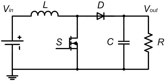
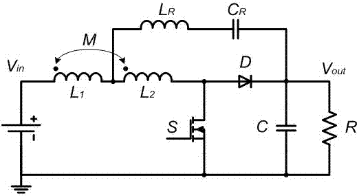
[0015] Such as figure 2 As shown, the present invention discloses a switching power supply for realizing low input current ripple, including a boost circuit and a ripple cancellation branch, the boost circuit includes a center-tapped inductance module of an input filter inductor, and the ripple The offsetting branch is bridged between the output end of the boost circuit and the middle tapped inductance module of the input filter inductance.

[0016] The center-tapped inductance module of the input filter inductance is composed of an inductance L1, an inductance L2, and a mutual inductance M connected in series.

[0017] The ripple cancellation branch includes an auxiliary inductance L connected in series R and storage capacitor C R composition.

[0018] The boost circuit further includes a switch S, a capacitor C, and a resistor R, and the switch S, the capacitor C, and the resistor R are connected in parallel with each other.

[0019] The boost circuit further includes a...


PUM


Abstract

The present invention provides a switching power supply for realizing low input current ripple, which includes a boost circuit and a ripple canceling branch. A center-tapped inductance module connected between the output end of the boost circuit and the input filter inductance. The beneficial effect of the present invention is that the present invention realizes the switching power supply with low input current ripple, draws out the middle tap from the input filter inductance of the traditional step-up circuit, and cooperates with the auxiliary inductance and energy storage capacitor with small volume and weight, namely It can ensure that the converter not only has low input current ripple, but also has high dynamic response. The switching power supply with low input current ripple has a simple structure, flexible design and adjustment, and strong practicability.

Description

technical field [0001] The invention relates to a switching power supply, in particular to a switching power supply realizing low input current ripple. Background technique [0002] In the traditional step-up switching power supply design, in order to ensure low input current ripple, a single-stage or multi-stage filtering link is usually added at the input end, or a two-phase interleaving method is used to achieve mutual cancellation of the input current. Its structure is as follows: figure 1 As shown, Vin is the input voltage, Vout is the output voltage, L is the input filter inductance, and D is the freewheeling diode. The traditional step-up circuit is formed by the above devices. [0003] In the actual design process of low input current ripple switching power supply, in order to ensure that the input current ripple is small, it is necessary to select a larger input filter inductance L, at this time the dynamic characteristics of the circuit will slow down due to the in...

Claims


Application Information

Patent Timeline
Patent Type & Authority Patents(China)
IPC IPC(8): H02M1/14
Inventor 张东来谷雨
Owner HARBIN INST OF TECH SHENZHEN GRADUATE SCHOOL
Why Eureka
Try Eureka