Switched reluctance motor torque ripple and bus current ripple suppression method

A switched reluctance motor and torque pulsation technology, which is applied in the direction of motor generator control, AC motor control, electronic commutation motor control, etc., can solve the problems of shortened life, large impact current of supporting capacitors, and inability to take into account bus current pulsation, etc. problem, to achieve the effect of simple control logic, direct suppression of torque ripple, and obvious suppression effect

Pending Publication Date: 2022-05-24
NORTHWESTERN POLYTECHNICAL UNIV
View PDF5 Cites 0 Cited by
  • Summary
  • Abstract
  • Description
  • Claims
  • Application Information

AI Technical Summary

Problems solved by technology

However, most of the methods are only aimed at the suppression of torque ripple, but cannot take into account the bus cu

Method used


Image

  • Switched reluctance motor torque ripple and bus current ripple suppression method
  • Switched reluctance motor torque ripple and bus current ripple suppression method
  • Switched reluctance motor torque ripple and bus current ripple suppression method

Examples


Embodiment Construction

[0046] The following in conjunction with the accompanying drawings and specific examples, the technical solution of the present invention is described in detail. The motor used in the example is a 1kW three-phase 12 / 8 pole switched reluctance motor.

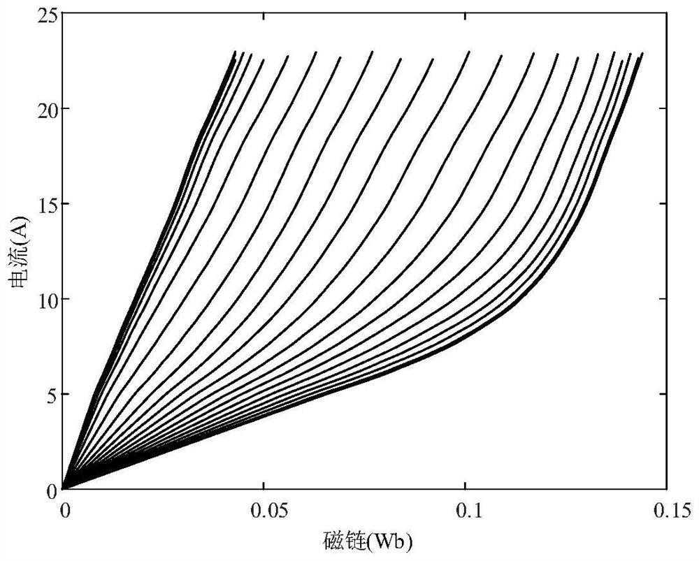
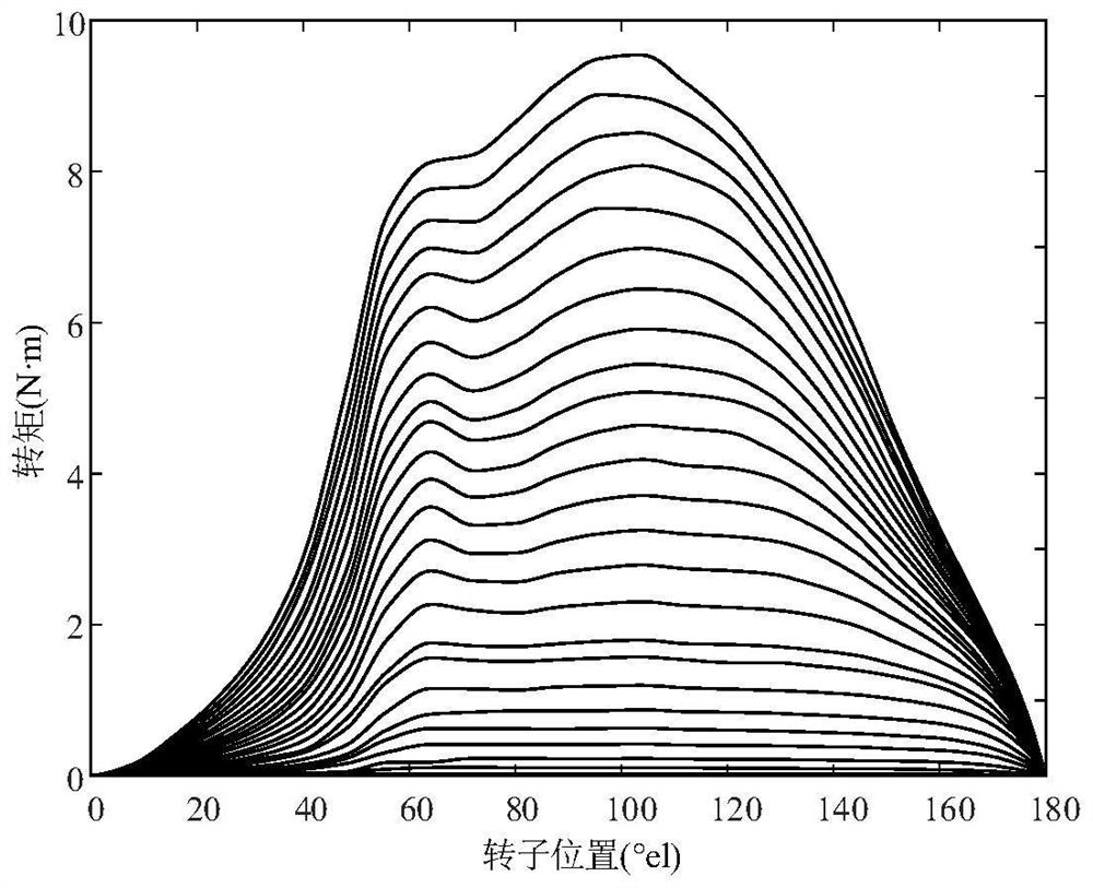
[0047] Step 1: Experimentally measure the flux characteristics and torque characteristics of the switched reluctance motor; obtain the flux characteristics ψ (i, θ) of the switched reluctance motor by the rotor fixation clamping method, wherein the ψ is the flux, i is the current, and θ is the position; the current lookup table i (ψ, θ) is constructed by interpolation method. On the basis of the flux characteristics, the torque data table T(i,θ) is constructed according to the bias of the position of the magnetic resonance energy. Characteristics of the flux, current and torque such as Figure 1-3 as shown. The formula for calculating magnetic common energy W′ is shown in equation (1), and the formula for torque T is shown in equation...


PUM


Abstract

The invention discloses a switched reluctance motor torque ripple and bus current ripple suppression method. According to the method, the flux linkage characteristic and the torque characteristic of the switched reluctance motor need to be obtained through off-line measurement. A total torque reference value is output by a speed proportional-integral controller, and a reference torque value of each phase is calculated by a torque distribution function. And according to the position and current information at the moment k and the position information stored at the moment k-1, calculating flux linkage and current information at the moment k + 1 in combination with an optimal switching vector calculated at the previous moment, and carrying out delay compensation. On the basis, position information at the k + 2 moment and flux linkage current information under an available switching vector are predicted, then a table is looked up to obtain torque and inverter input current values under each switching state, the torque and the inverter input current values are substituted into a cost function, the operation state with the minimum cost function value serves as a switching signal, and the switching signal is applied to a control power converter; therefore, the effect of suppressing the torque ripple and the bus current ripple at the same time is achieved. The effectiveness of the method is verified through simulation, the control logic of the method is simple, the torque ripple and bus current ripple suppression effect is obvious, and the impact of bus current on the supporting capacitor is effectively reduced.

Description

Technical field [0001] The present invention relates to a switching reluctance motor torque ripple and busbar current ripple suppression method, belongs to the field of motor control. Background [0002] Due to its simple structure, wide speed regulation range and low production cost, switched reluctance motor has a wide range of application prospects in aerospace, electric vehicles, wind power generation and other fields. However, the unique biconvex pole structure causes its commutation torque to ripple largely, which seriously affects its control performance. The researchers have conducted a large number of studies on the torque ripple suppression method and proposed a series of control strategies, such as direct torque control, direct instantaneous torque control, torque allocation function, iterative learning, etc. However, most methods only aim at the suppression of torque ripple, and cannot take into account the busbar current ripple, resulting in the support capacitance o...

Claims


Application Information

Patent Timeline
IPC IPC(8): H02P21/18H02P21/14H02P21/22H02P25/098H02P27/06
CPCH02P21/18H02P21/14H02P21/141H02P21/22H02P25/098H02P27/06
Inventor 葛乐飞钟继析刘家羽谢晨阳高靖博宋受俊
Owner NORTHWESTERN POLYTECHNICAL UNIV
Why Eureka
Try Eureka