Filtering signals

Inactive Publication Date: 2005-07-21
NOKIA SOLUTIONS & NETWORKS OY
View PDF7 Cites 18 Cited by
  • Summary
  • Abstract
  • Description
  • Claims
  • Application Information

AI Technical Summary

Benefits of technology

[0029] The present invention has significant advantages compared with prior art solutions. By careful frequency planning the inband interferers can be avoided and the receiver architecture with a controllable intermediate frequency polyphase filter gives some more freedom for the frequency planning of the system by providing a way to get the receiver more tolerant against narrowband interference in e.g. a multistandard environment. A

Problems solved by technology

In some present receivers the bandwidth of the front-end analog IF filter is not calibrated due to minimization of the chip area and the cost.
When such a receiver is placed in a device comprising a transmitter transmitting signals on a frequency band near the receiving frequency band of the receiver, a disturbing signal (a jamming signal) may exist in the input of the receiver that is outside the actual signal band but still in the received analog band.
This is due to the fact that the disturbing signal is not attenuated enough and when the received signals are downconverted by a local oscillator to the IF frequency band also the disturbing signal is downconverted to the IF frequency band.
After the downconversion it is almost impossible to separate the disturbing signal from the actual signal.
As a result the transmitter of the mobile communication device may cause disturbing signals to the satellite positioning system receiver.
Another cause of jamming can be due to signals generated in the mobile communication receiver.
The frequency of the local oscillator signals or some harmonic components of the local oscillator signals or reference crystal oscillator signals may couple to the RF input of the satellite positioning system receiver and can generate spurious signals or other disturbances in the satellite positionin

Method used


Image

  • Filtering signals
  • Filtering signals
  • Filtering signals

Examples


Embodiment Construction

[0040] In the following, the present invention will be described in more detail husing the electronic device 50 of FIG. 5 as an example. The electronic device 50 comprises a receiver 51 in which a filter 14 according to an embodiment of the present invention is utilized. The details of the receiver 51 and the filter 14 are depicted in FIGS. 2, 3, 4a and 4b.

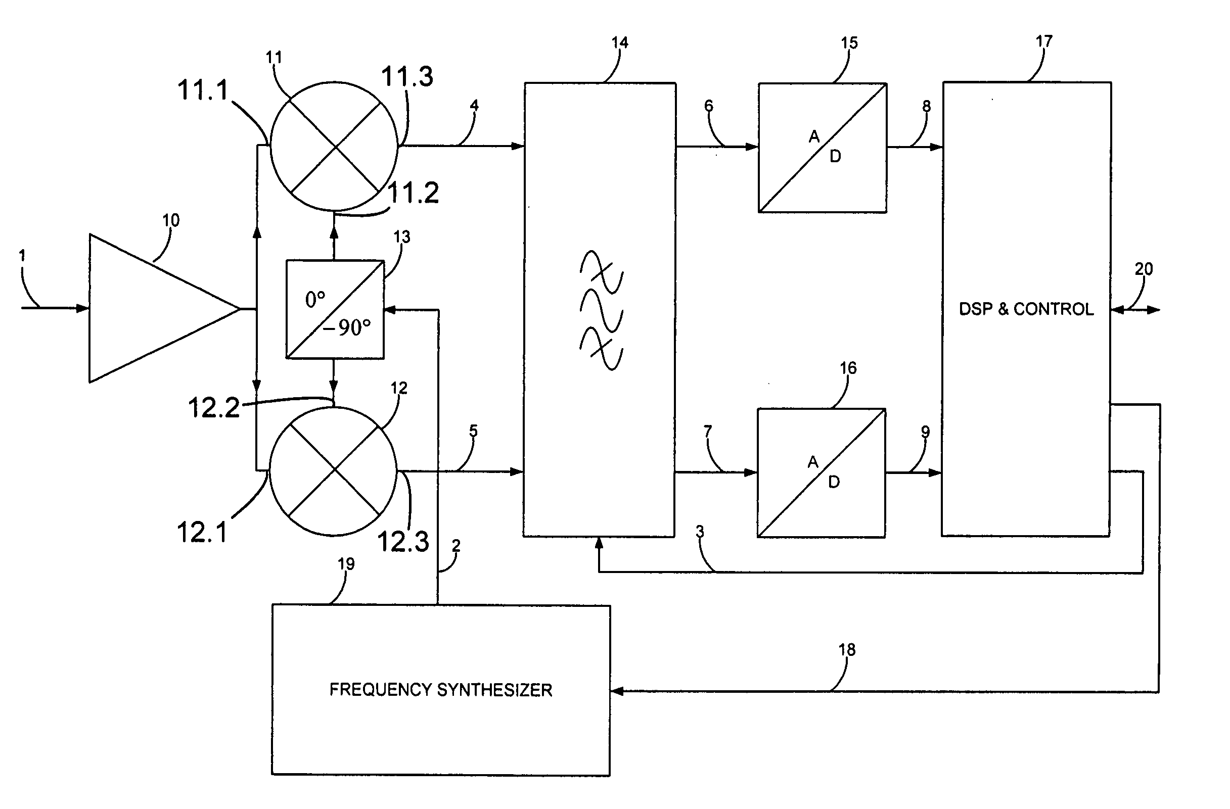
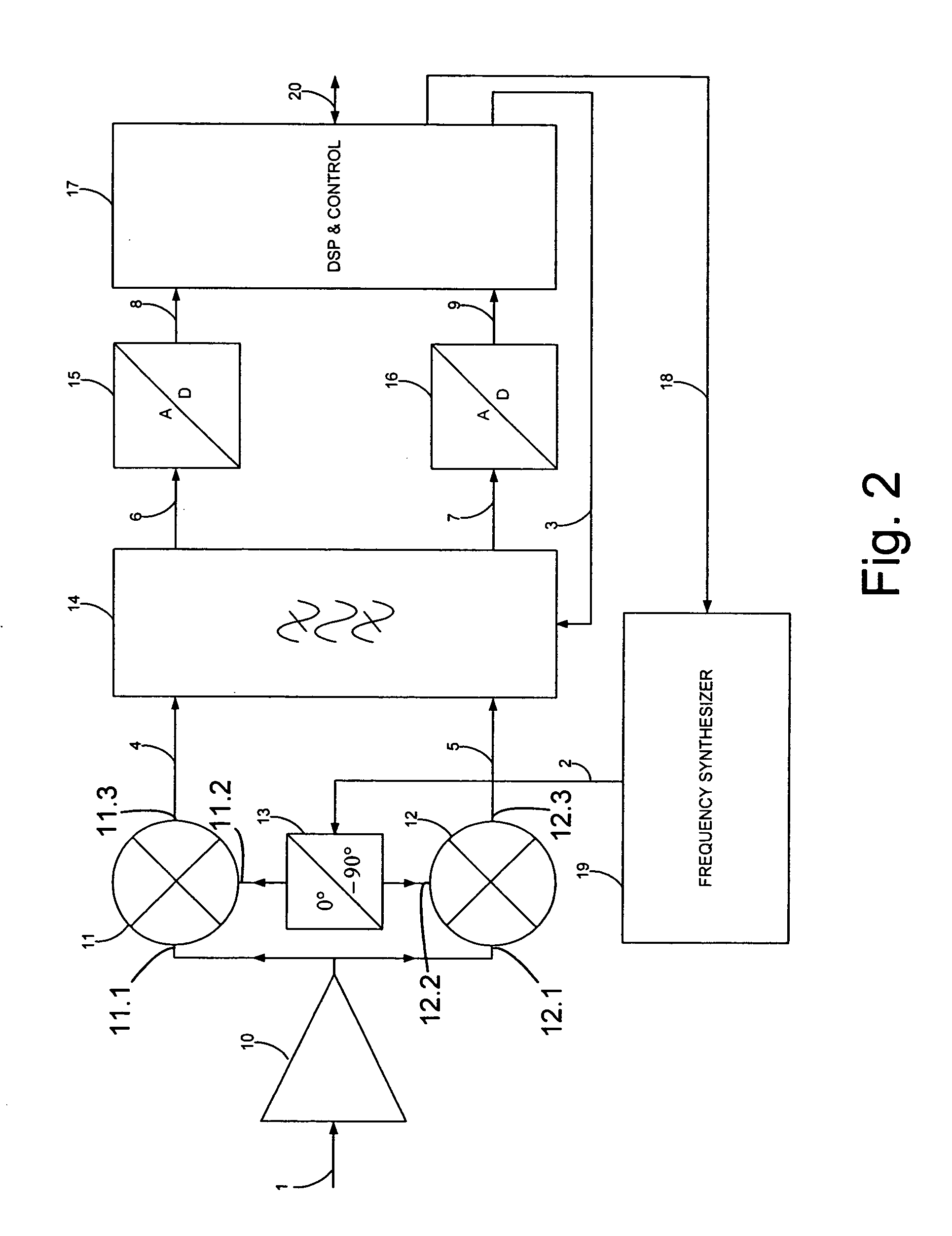
[0041] Radio frequency signals are received by an antenna 52 and led to the input 1 (the front-end) of the receiver 51 through a bandpass filter 53 (FIG. 5). The bandpass filter 53 is used to filter out signals which are outside the frequency band of the wanted signals. However, the bandwidth of the filter is broader than the bandwidth of the actual signals as was already mentioned above in the description. Referring now to FIG. 2, the received signals passed through the antenna coupler 53 are amplified by the low noise high frequency amplifier 10. After that, the amplified signals are directed to a first input 11.1 of a first mi...


PUM


Abstract

The invention relates to an IF polyphase filter for filtering received RF signals. The signals are downconverted into intermediate frequency signals before filtering them in the IF polyphase filter. The IF polyphase filter comprises means for defining a passband for the IF polyphase filter. The IF polyphase filter further comprises a passband adapting element for setting the passband of the IF polyphase filter in positive or in negative frequencies. The invention further relates to a receiver comprising the IF polyphase filter according to the invention. The invention further relates to a method for filtering received RF signals by using an IF polyphase filter. The method comprises downconverting the received RF signals into intermediate frequency signals before filtering them in the IF polyphase filter, and defining a passband for the IF polyphase filter. The passband of the IF polyphase filter is set in positive or in negative frequencies.

Description

CROSS-REFERENCE TO RELATED APPLICATIONS [0001] This application claims priority under 35 USC §119 to Finnish Patent Application No. 20035209 filed on Nov. 14, 2003. FIELD OF THE INVENTION [0002] The present invention relates to an intermediate frequency (IF) polyphase filter for filtering received radio frequency (RF) signals downconverted into intermediate frequency signals, comprising means for defining a passband for the IF polyphase filter. The invention also relates to a receiver comprising at least an input for receiving RF signals, downconverting means for downconverting the received RF signals into intermediate frequency signals, and an IF polyphase filter for filtering the intermediate signals to separate wanted signals from disturbing signals. The invention also relates to a device comprising a receiver, which comprises at least an input for receiving RF signals, downconverting means for downconverting the received RF signals into intermediate frequency signals, and an IF ...

Claims


Application Information

Patent Timeline
IPC IPC(8): H04B1/28
CPCH04B1/28H04B1/0007
Inventor VAANANEN, PAAVO
Owner NOKIA SOLUTIONS & NETWORKS OY
Why Eureka
Try Eureka