Vertical takeoff and landing vehicle

a vertical takeoff and landing technology, applied in the field of air systems, can solve the problems of reducing the lift of the aircraft, reducing the flight performance of the craft, and presenting the same danger of losing lift as tilt-rotor aircra

Active Publication Date: 2019-07-16
DIVERGING TECH LLC
View PDF13 Cites 17 Cited by
  • Summary
  • Abstract
  • Description
  • Claims
  • Application Information

AI Technical Summary

Benefits of technology

[0022]A method of controlling the propulsion systems utilizing a more intuitive control logic than known in the prior art is also provided. By providing an aircraft with propulsion systems that are grouped for control in view of their position on the aircraft, for example front-back groups or left-right groups, control logic can be deployed that can adjust roll, pitch, and yaw of the craft without altering the spatial aerial location of the aircraft (i.e. during hover). The control logic can also adjust the roll, pitch, and yaw of the craft without altering the velocity vector of the aircraft (i.e. during forward or rearward flight).

Problems solved by technology

A significant drawback that this design produces is an inherent “danger zone” of time, whereby the lift of the aircraft is reduced as its wings and propellers are rotated from the horizontal “hover” position to the vertical “flight” position.
The same danger of losing lift as experienced by tilt-rotor aircraft is present with the redirected thrust vehicles.
The angle of all the blades may be changed simultaneously (termed collective control) to avoid the added complexity of changing the angle of each blade individually (termed cyclic control), but this may reduce the performance of the craft in flight.
The disadvantage of using collective controls, and especially cyclic controls, lies in their added complexity, weight and cost.

Method used


Image

  • Vertical takeoff and landing vehicle
  • Vertical takeoff and landing vehicle
  • Vertical takeoff and landing vehicle

Examples


Embodiment Construction

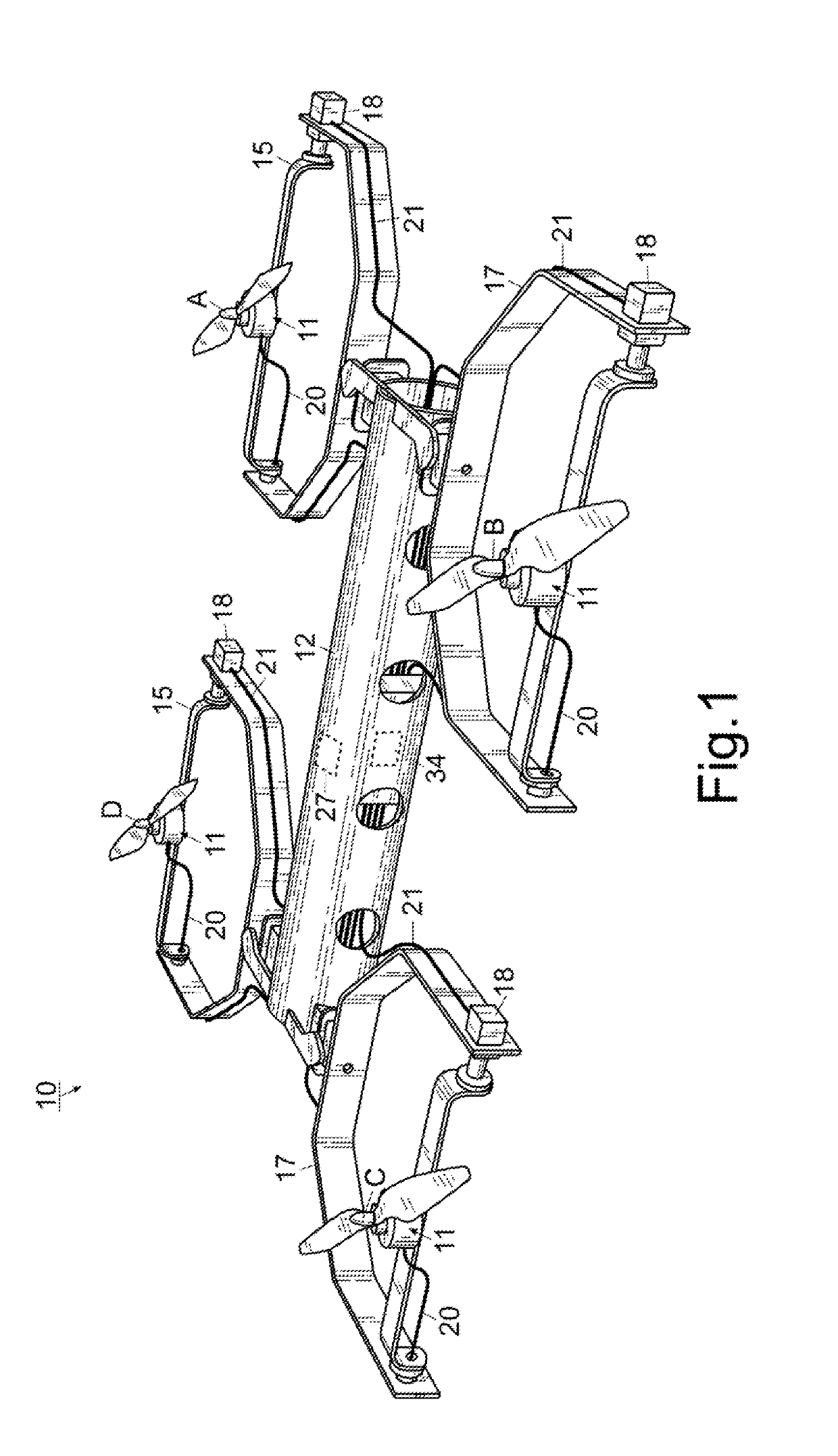
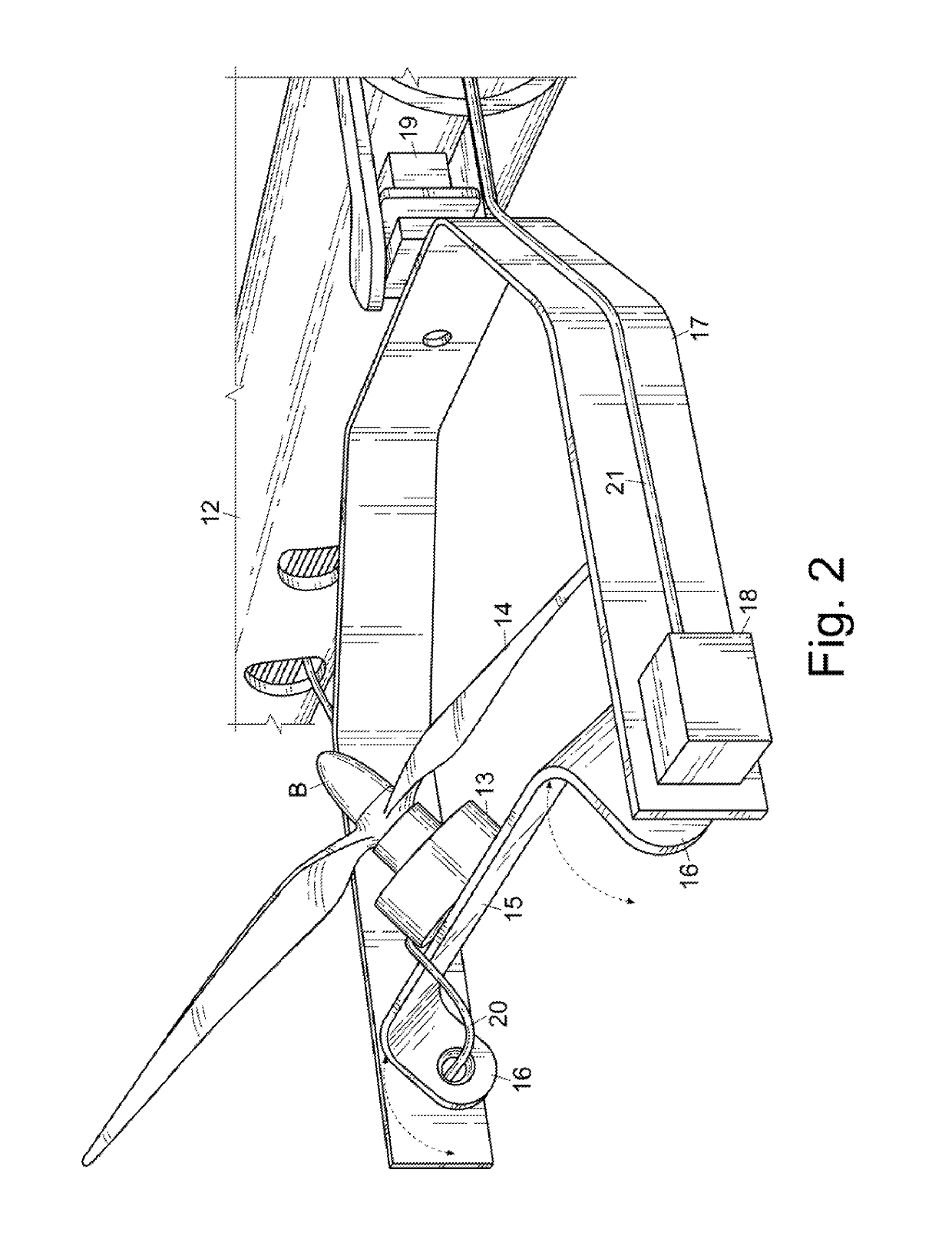
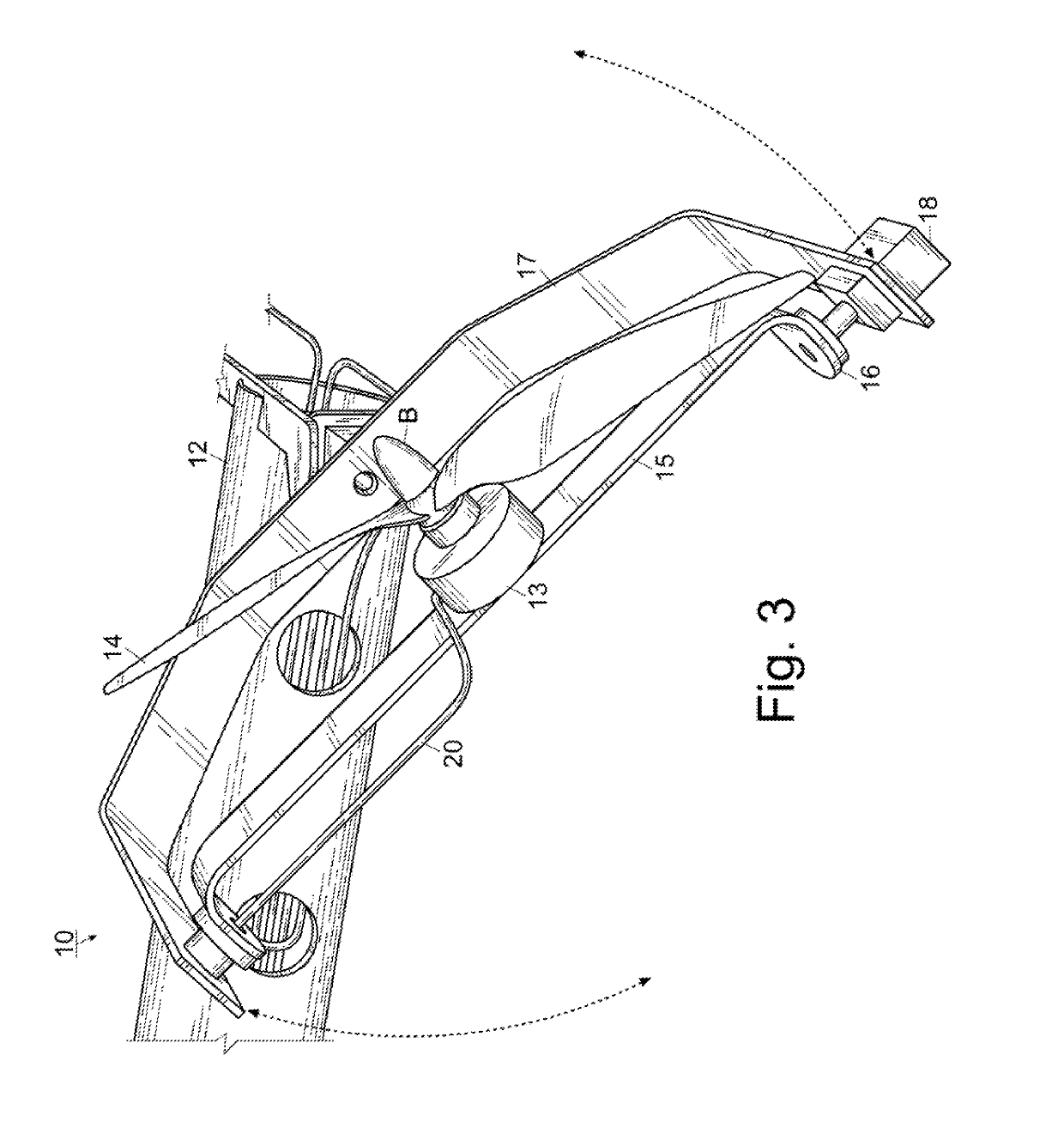
[0030]For a better understanding of the invention and its operation, turning now to the drawings, FIGS. 1-3 show preferred aircraft 10 with a plurality of propulsion systems 11 positioned about the outboard periphery of airframe 12. Preferred propulsion system 11 is a ducted fan oriented with the openings perpendicular to the horizon (not shown), directing thrust along a vertical vector, but other propulsion members such as jet turbines, ducted fans with an end closed, pulse detonation engines, a-typical gear turbine engines, electrostatic ion thrusters, conventional propellers (as illustrated in FIGS. 1-3 for clarity and ease of demonstration), Sonic Blue electric S-MAGJET engines, Boeing PETA pulse jets, Pratt & Whitney PURE POWER P1000G engines, or the like may also be utilized in a similar manner. Regardless of the specific propulsion system 11, one or more propulsion systems 11 are mounted to airframe 12 and preferably two or more propulsion systems 11 for performance and redun...


PUM


Abstract

An aircraft capable of vertical takeoff and landing (VTOL) including one or more propulsion systems gyroscopically mounted (i.e. rotatable about x- and y-axes) to a rigid airframe is disclosed. Each “wing” includes a propulsion system mounted to an axle that is rotatably attached to a wing mount, which in turn is pivotably mounted to the exterior of the airframe. The propulsion systems are electronically grouped according to their position relative to the airframe, such that one controller can control all the propulsion systems on the right or left side of the aircraft, resulting in control logic that is far more intuitive and convenient than that taught in the prior art. A method of operating an aircraft utilizing this improved control logic is also disclosed.

Description

[0001]This non-provisional patent application claims all benefits under 35 U.S.C. § 119(e) of U.S. provisional patent application Ser. No. 62 / 166,908 filed 27 May 2015, entitled “VERTICAL TAKEOFF AND LANDING AIRCRAFT”, in the United States Patent and Trademark Office, which is incorporated by reference in its entirety herein.FIELD OF THE INVENTION[0002]The invention herein pertains to air systems and particularly pertains to a vertical takeoff and landing (VTOL) aircraft utilizing a specialized air frame in combination with controls more intuitive than those taught in the prior art to produce unexpected maneuverability and performance.DESCRIPTION OF THE PRIOR ART AND OBJECTIVES OF THE INVENTION[0003]As the cost and security concerns associated with runways have increased, the need for aircraft that do not require them has become more acute. Vertical takeoff and landing (VTOL) aircraft are known in the art as a solution to reduce the reliance on runways while maintaining the range an...

Claims


Application Information

Patent Timeline
Patent Type & Authority Patents(United States)
IPC IPC(8): B64C13/04B64C13/12B64C27/20B64C29/00B64C3/38
CPCB64C29/0033B64C13/04B64C3/38B64C13/12B64C27/20B64C2201/146B64C2201/027B64C39/024B64C27/08B64C27/52B64U10/13B64U30/20B64U2201/20
Inventor DENNIS, JEREMY
Owner DIVERGING TECH LLC
Why Eureka
Try Eureka