Force feedback device

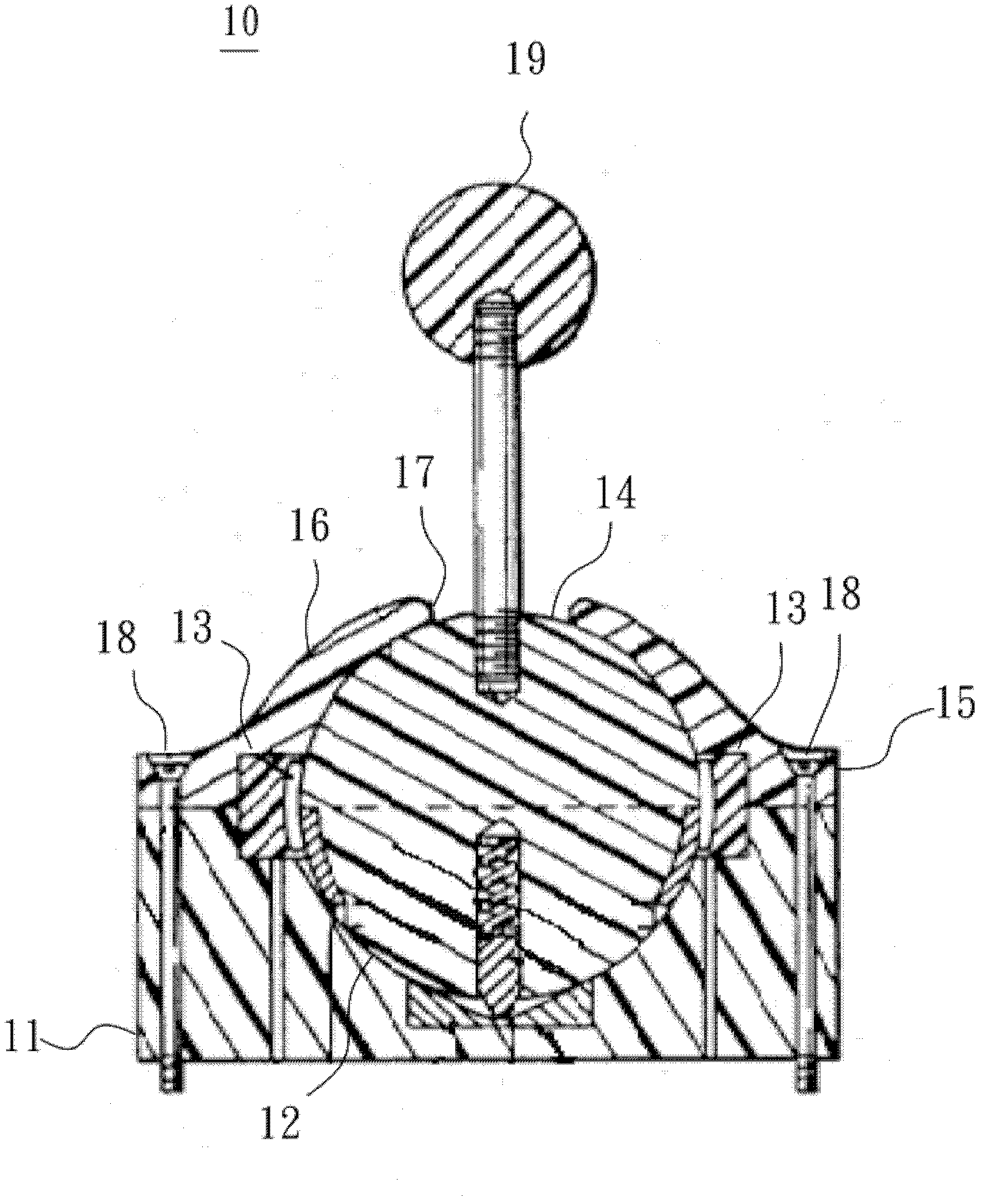
A technology of shafts and slots, applied in mechanical control devices, devices for preventing/restricting/restoring the movement of parts of the control mechanism, and manually operated control mechanisms, can solve the problem of reducing the movement precision of the rocker 19 and affecting the rocker Problems such as the operating feel of the rod 19 and the impossibility of precise positioning of the ball 14

Inactive Publication Date: 2013-07-03
QUANTA STORAGE INC
View PDF5 Cites 14 Cited by
  • Summary
  • Abstract
  • Description
  • Claims
  • Application Information

AI Technical Summary

Problems solved by technology

[0004] However, the groove 12 and the top cover 16 of the prior art force feedback device 10 need to be spherically covered to support the rotation of the ball 14.
Due to the manufacturing difficulties and tolerances of the roundness, after the assembly is completed, the gap between the ball 14 and the groove 12 and the top 16 may be too large or too tight
If the gap is too large, the ball 14 cannot be positioned accurately, reducing the movement precision of the rocker 19, while if the gap is too tight, the ball 14 will not easily slide, affecting the operating feel of the rocker 19
Especially for force feedback devices with multi-axis control, the aforementioned problems are more serious due to the need for multi-layer stacking of axes
Therefore, there are still problems to be solved urgently in the assembly structure of the force feedback device

Method used


Image

  • Force feedback device
  • Force feedback device
  • Force feedback device

Examples


Embodiment Construction

[0041] In order to achieve the above object, the present invention adopts the technical means and its effects, hereby give preferred embodiments, and illustrate as follows in conjunction with the accompanying drawings.

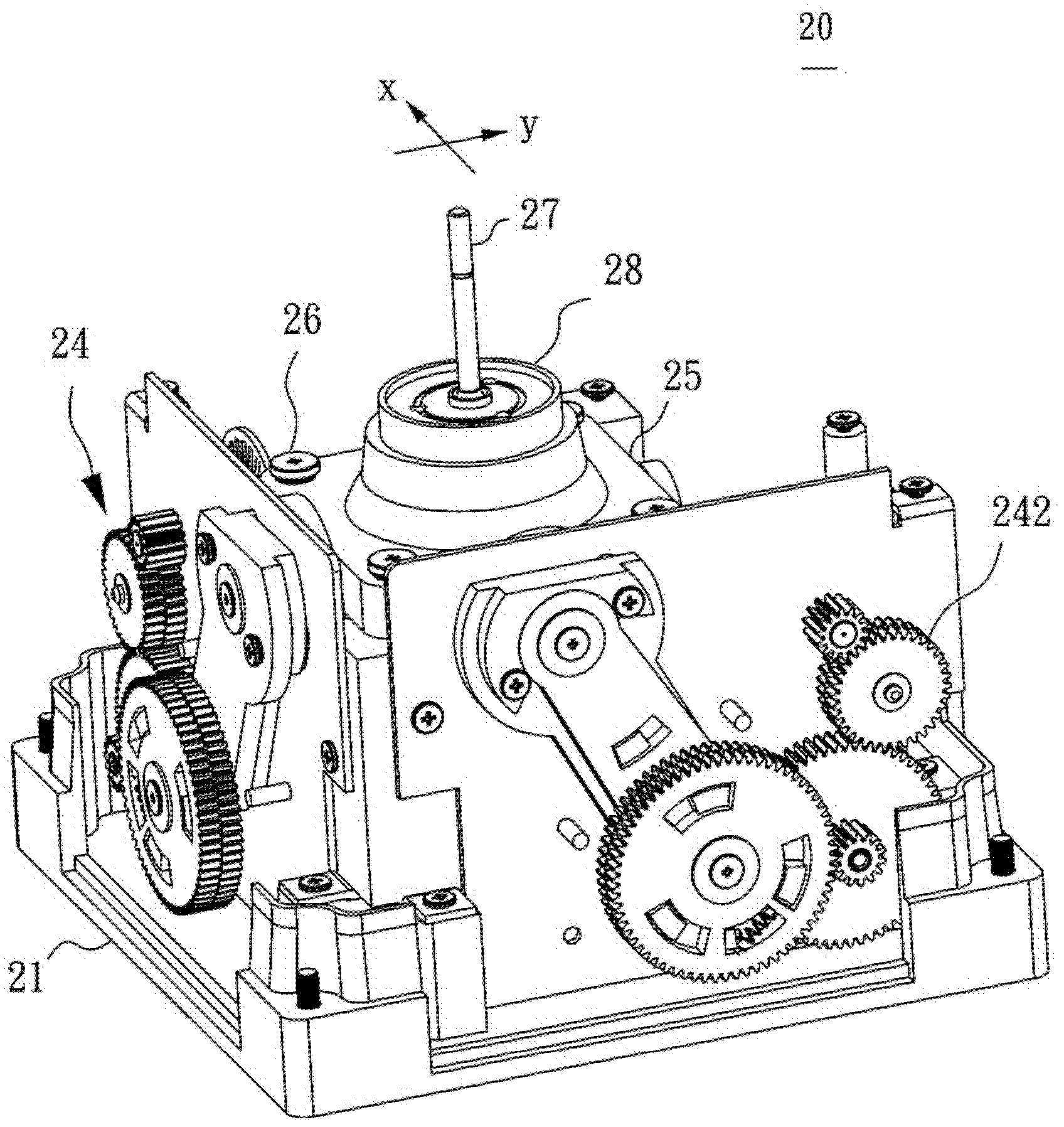
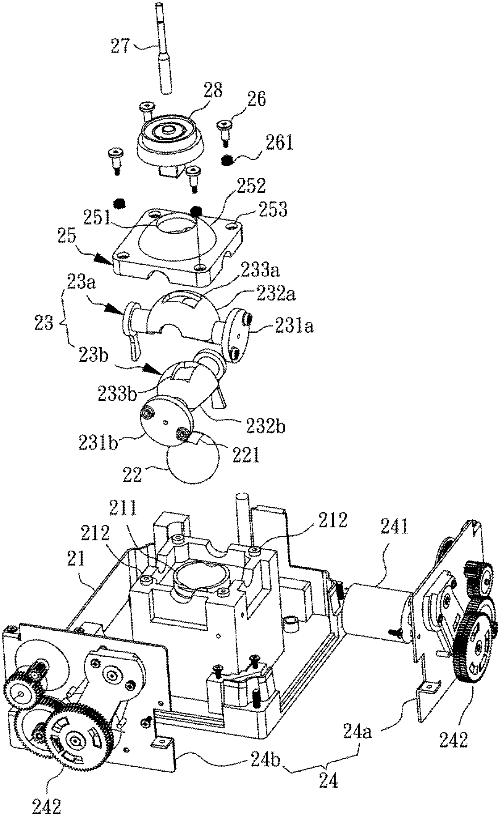
[0042] see figure 2 and image 3 , figure 2 is a perspective view of the force feedback device 20 according to the first embodiment of the present invention, image 3 It is an exploded view of the force feedback device 20 according to the first embodiment of the present invention. The force feedback device 20 of the present invention mainly includes a base 21 , a ball 22 , a shaft unit 23 , a force feedback unit 24 , a top cover 25 , a combined bolt 26 and a rocker 27 . Wherein, a groove 211 is recessed on the base 21 , and several screw holes 212 are respectively arranged around the groove 211 . The ball 22 is arranged to rotate in the groove 211 , and a coupling hole 221 is arranged on the ball 22 .

[0043] The shaft unit 23 includes at least one sha...


PUM


Abstract

The invention discloses a force feedback device which is characterized in that a plurality of assembling bolts are provided with springs in a sleeving manner, penetrate through top pressure groove holes around a top cap, and lock the top cap into a base. The springs are stayed in the step-shaped top pressure groove holes and extruded among bolt heads of the assembling bolts and the top cap, and absorption gaps are reserved among the bolt heads and the top cap due to the fact that the bolt body height of each assembling bolt is greater than the predetermined height of each top pressure groove hole, so that the operation of a rocker is smooth.

Description

technical field [0001] The invention relates to a force feedback device, in particular to a joystick used in games or vehicles to operate an input interface for multi-axis control. Background technique [0002] The Force Feedback Device (Force Feedback Device) mainly uses the joystick to operate the multi-axis displacement, which requires precise movement control and smooth operation feel to correctly control the positioning of the object. [0003] Such as figure 1 As shown, the US4733214 patent case published by the United States discloses the force feedback device 10 of the prior art. A groove 12 is formed on the base 11, and a sensor 13 is arranged around the groove 12, and a ball 14 is placed in the ball 14. The outer diameter matches the profile of the groove 12. Cover top cover 15 on ball 14 again, top cover 15 has top cover 16, and top cover 16 center establishes operating hole 17, and top cover 16 inner side profile coordinates the external diameter of ball 14. Th...

Claims


Application Information

Patent Timeline
Patent Type & Authority Applications(China)
IPC IPC(8): G05G5/06G05G9/047A63F13/02
CPCA63F13/285A63F13/24G05G9/047
Inventor 张友铭吴仁琛
Owner QUANTA STORAGE INC
Why Eureka
Try Eureka