
Directional cover pressing device for flow guide groove cover

A diversion tank cover and capping technology, which is applied in the direction of flanged bottle caps, etc., can solve the problems of inability to adapt to automation, large-scale production, low production efficiency, and high labor intensity, so as to achieve ingenious structural design and improve production efficiency , to meet the effect of automation

Active Publication Date: 2014-08-13
JIANGSU TOM PACKAGING MACHINERY
View PDF5 Cites 0 Cited by
  • Summary
  • Abstract
  • Description
  • Claims
  • Application Information

AI Technical Summary

Problems solved by technology

The installation of the current diversion tank cover is usually done manually or by machine, which is labor-intensive and inefficient
The capping machine for the diversion groove cap is a device that can install the diversion groove cap on the bottle body, but due to the particularity of the structure of the diversion groove cap, the existing diversion groove cap capping machine cannot guarantee that each capping The orientation of the diversion tank cover is consistent, so manual adjustment is still required, resulting in time-consuming and labor-consuming, low production efficiency, and cannot meet the requirements of automation and large-scale production

Method used


Image

  • Directional cover pressing device for flow guide groove cover
  • Directional cover pressing device for flow guide groove cover
  • Directional cover pressing device for flow guide groove cover

Examples


Embodiment 1)

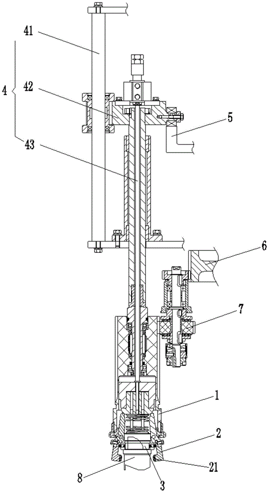
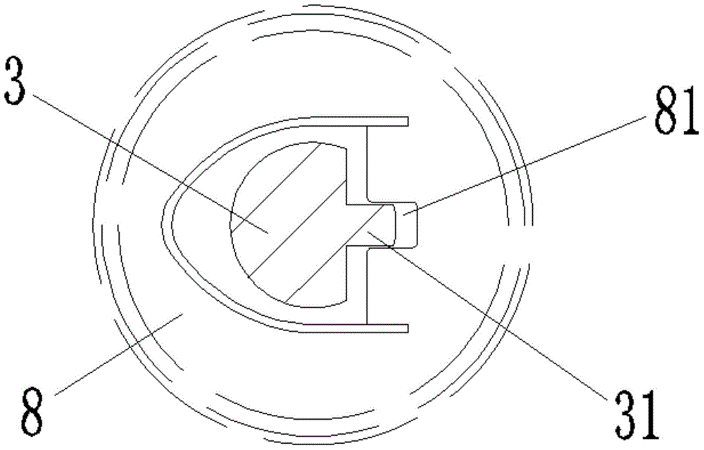
[0027] See figure 1 , The orientation capping device of the diversion tank cover of the present embodiment includes a cover claw seat 1, a cover claw 2, an orientation block 3, a lifting mechanism 4, a lifting driving mechanism and a rotating driving mechanism. Get the bottom of cover pawl seat 1 and lifting mechanism 4 to be rotatably connected. Get the lid claw 2 and be fixed on the bottom of getting the lid claw seat 1. The orientation block 3 is fixed on the bottom of the lifting mechanism 4 and is located in the cover pawl 2 . The lifting drive mechanism drives the lifting mechanism 4 to drive the lid claw seat 1 to perform lifting motion. The rotation drive mechanism drives the cover claw seat 1 to rotate.

[0028] The lifting mechanism 4 includes a lifting bracket 41 , a lifting block 42 and a lifting link 43 . The lifting block 42 is slidably connected with the lifting bracket 41 in the vertical direction. The top of the lifting link 43 is fixed on the lifting blo...

Embodiment 2)

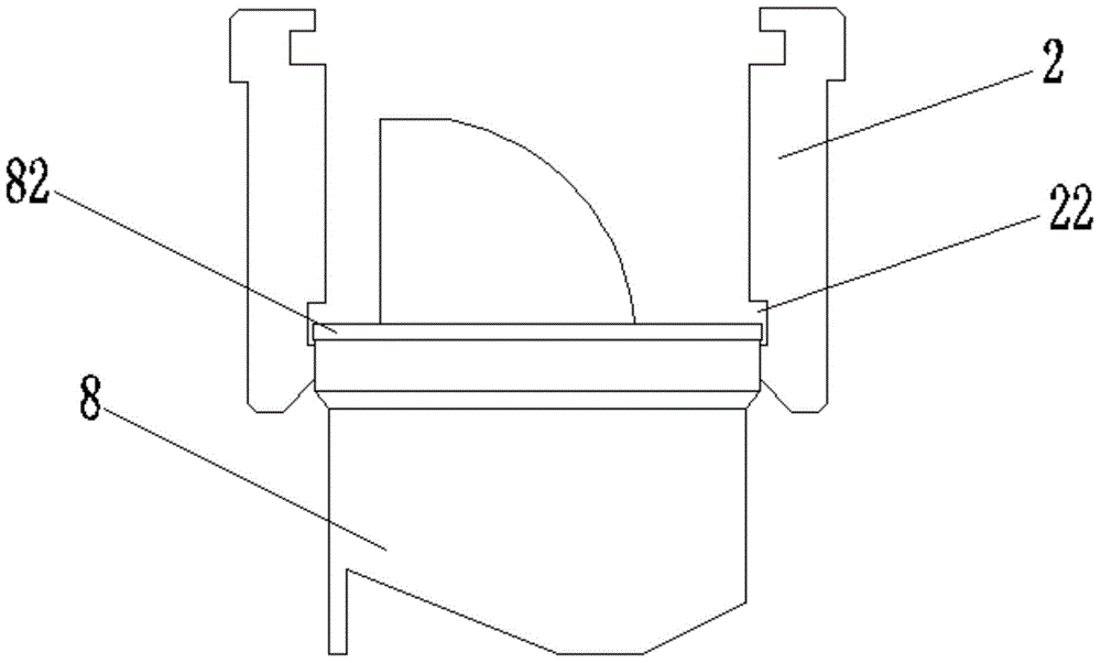
[0034] See image 3 , this embodiment is basically the same as Embodiment 1, the difference is that the cover claw 2 is provided with an inner hook groove 22 that cooperates with the outer wall flange 82 of the diversion tank cover 8 .

Embodiment 3)

[0036] This embodiment is basically the same as Embodiment 1, the difference is that: the cover claw 2 is provided with an outer hook groove that can cooperate with the inner wall flange of the diversion tank cover 8 .


PUM


Abstract

The invention discloses a directional cover pressing device for a flow guide groove cover. The directional cover pressing device comprises a cover taking claw seat, a cover taking claw, a directional block, a lifting mechanism, a lifting driving mechanism and a rotating driving mechanism. The cover taking claw seat is rotatably connected with the lower portion of the lifting mechanism, the cover taking claw is fixed on the lower portion of the cover taking claw seat, the directional block is fixed at the bottom of the lifting mechanism and located in the cover taking claw, the lifting driving mechanism drives the lifting mechanism to drive the cover taking claw seat to lift, and the rotating driving mechanism drives the cover taking claw seat to rotate. By arranging the directional block, the flow guide groove cover can be kept consistent in orientation prior to cover pressing operation, orientation consistence is guaranteed after cover pressing is finished, and the directional cover pressing device is ingenious in structural design, improves production efficiency and meets the requirements of automated large-scale production.

Description

technical field [0001] The invention relates to an orientation capping device for a diversion tank cover. Background technique [0002] At present, in daily chemical and other industries, many products use diversion tank covers. The installation of the current diversion tank cover is usually carried out manually or by machine, which is labor intensive and inefficient. The capping machine for the diversion groove cap is a device that can install the diversion groove cap on the bottle body, but due to the particularity of the structure of the diversion groove cap, the existing diversion groove cap capping machine cannot guarantee that each capping The orientation of the diversion tank cover is consistent, so manual adjustment is still required, resulting in time-consuming and labor-consuming, low production efficiency, and cannot meet the requirements of automation and large-scale production. Contents of the invention [0003] The technical problem to be solved by the pres...

Claims


Application Information

Patent Timeline
Patent Type & Authority Patents(China)
IPC IPC(8): B67B3/10
Inventor 徐根宝汤建华蔡健
Owner JIANGSU TOM PACKAGING MACHINERY
Learn More