

Roller brush lifting device
A lifting device and rolling brush technology, which is applied in road cleaning, construction, cleaning methods, etc., can solve the problems of cumbersome oil circuit system, poor reliability, and low rotation efficiency of pulleys
Inactive Publication Date: 2013-07-10
WUHU AIRUITE ENVIRONMENTAL TECH
View PDF5 Cites 10 Cited by
- Summary
- Abstract
- Description
- Claims
- Application Information
AI Technical Summary
Problems solved by technology
[0002] In the past, the roller brush electric lifting mechanism realized lifting through multi-stage connecting rods, cable pulleys and hydraulic push rods, but the multi-stage connecting rods and cable pulleys had low rotation efficiency and poor reliability; although the hydraulic push rods were reliable, the oil circuit system was cumbersome and difficult to maintain. It's not very convenient
Method used
View moreImage
Smart ImageViewing Examples

Examples
Embodiment Construction
[0008] The present invention will be further described in detail in conjunction with the accompanying drawings.
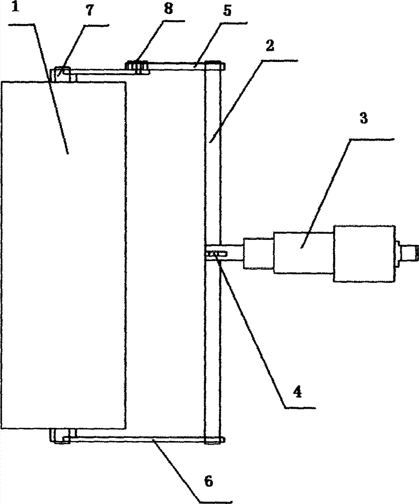
[0009] From figure 1 It can be seen that the rolling brush lifting device includes a rolling brush 1, a rolling brush lifting shaft 2, and an electric push rod 3. Rolling brush support 5,6 on both sides, rolling brush support 5,6 is connected to the axle center 7 of rolling brush respectively, and rolling brush support 5 is connected by two connecting rod supports, and connection point has hexagonal bolt 8.
Login to View More PUM
 Abstract
The invention discloses a roller brush lifting device. The roller brush lifting device comprises a roller brush, a roller brush lifting rotating shaft and an electric push rod; the electric push rod is connected with a bracket which is vertically and fixedly connected to the middle of the roller brush lifting rotating shaft; roller brush brackets are arranged on two sides of the roller brush lifting rotating shaft; the roller brush brackets are connected with an axle center of the roller brush; each roller brush bracket consists of two connecting rod brackets which are connected; and a hexagonal bolt is arranged at the connection point of the two connecting rod brackets. The invention adopts a simple and convenient method for lifting or descending the roller brush through the electric push rod and the control is sensitive. In order to conveniently change the roller brush, movable connection is adopted for the connecting rod brackets, so that the roller brush can be conveniently disassembled.
Description
technical field [0001] The invention relates to a roller brush lifting device on an electric cleaning vehicle. Background technique [0002] In the past, the roller brush electric lifting mechanism realized the lifting through multi-stage connecting rods, cable pulleys and hydraulic push rods, but the multi-stage connecting rods and cable pulleys had low rotation efficiency and poor reliability; although the hydraulic push rods were reliable, the oil circuit system was cumbersome and difficult to maintain. It is not very convenient. Contents of the invention [0003] The invention relates to a rolling brush lifting device with convenient rolling brush disassembly and free lifting. [0004] The purpose of the present invention is achieved through the following technical solutions: the rolling brush lifting device includes a rolling brush, a rolling brush lifting shaft, and an electric push rod. The roller brush brackets on both sides of the rotating shaft are respectively...
Claims
Login to View More Application Information
Patent Timeline
 Patent Type & AuthorityApplications(China)
IPC IPC(8): E01H1/05
Inventor艾和金杨金树王家梅邵和胜陈永祥
OwnerWUHU AIRUITE ENVIRONMENTAL TECH