Testing structure and testing method for micro-machine residual stress

A technology for testing structure and residual stress, applied in the direction of measuring force, measuring device, instrument, etc., can solve problems such as film structure warping, affecting film adhesion, affecting MEMS device performance, etc., and achieves the effect of improving accuracy and high precision

Inactive Publication Date: 2013-07-10
SOUTHEAST UNIV
View PDF5 Cites 8 Cited by
  • Summary
  • Abstract
  • Description
  • Claims
  • Application Information

AI Technical Summary

Problems solved by technology

The residual stress in the horizontal direction causes the thin film structure to deform horizontally after the release of the underlying sacrificial layer, and the uneven distribution of residual stress in the vertical direction will cause the warping of the thin film structure
Therefore, the size of the residual stress seriously affects the performance of MEMS devices, and also affects important characteristics such as adhesion and fracture of the film, thus bringing many problems to the production of MEMS devices with excellent performance.

Method used


Image

  • Testing structure and testing method for micro-machine residual stress
  • Testing structure and testing method for micro-machine residual stress
  • Testing structure and testing method for micro-machine residual stress

Examples


Embodiment Construction

[0026] The present invention will be further described below in conjunction with the accompanying drawings.

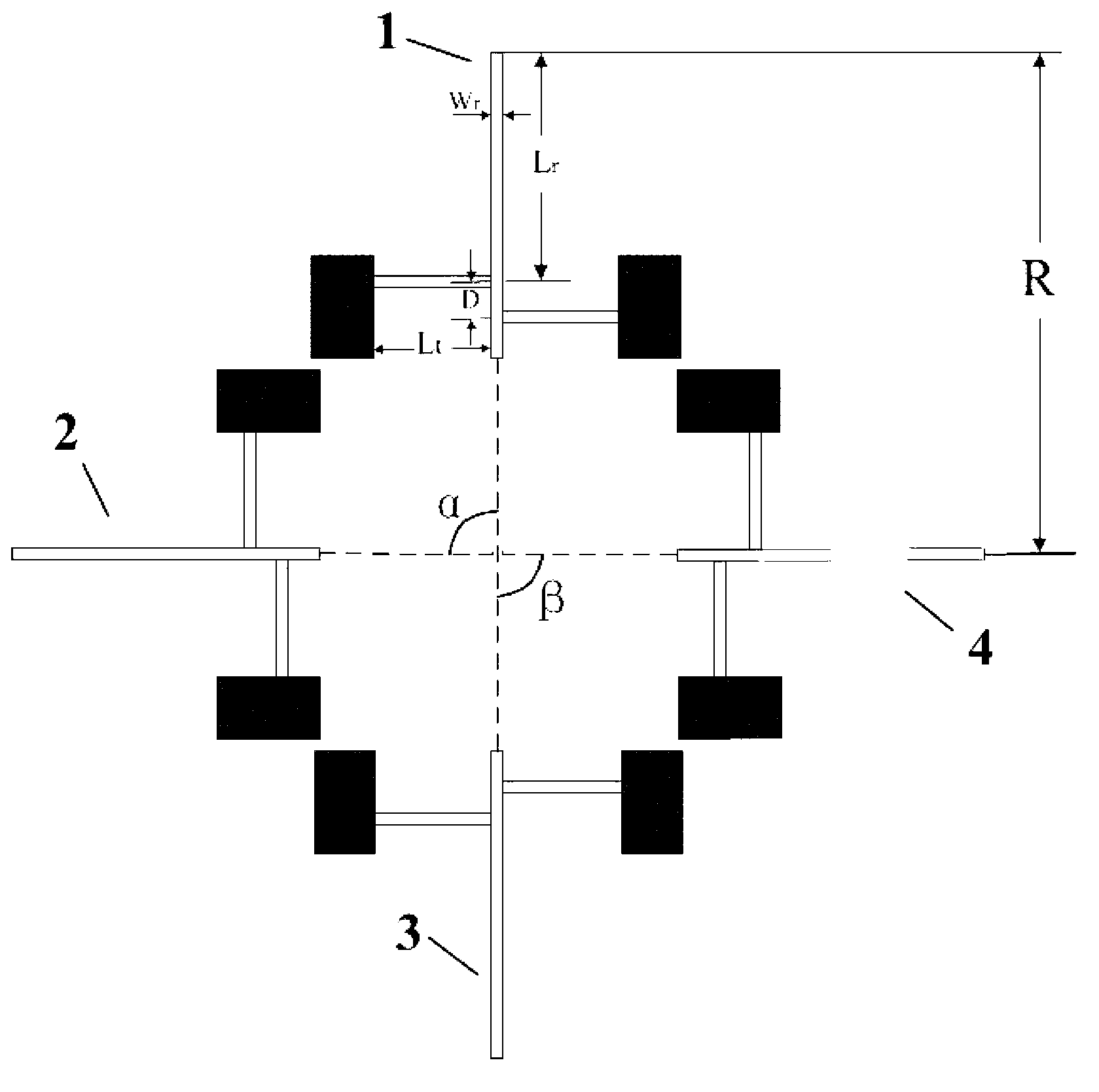
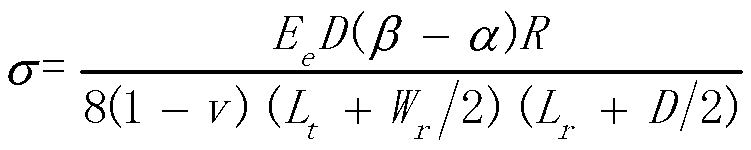
[0027] Such as figure 1 Shown is a micromechanical residual stress test structure, including four sets of micromechanical beam test structures with identical structural size parameters; the micromechanical beam test structure includes a pointer beam and two test beams with identical structural size parameters , the two test beams are parallel to each other and perpendicular to the pointer beam, the intersection between the pointer beam and the test beam is recorded as the rotation point; all the pointer beams and test beams of the four sets of micromechanical beam test structures are located at In the same vertical plane; record the pointer beams of the four sets of micromechanical beam test structures as No. 1 pointer beam, No. 2 pointer beam, No. 3 pointer beam and No. 4 pointer beam; the No. 1 pointer beam, No. 2 pointer beam Beam, No. 3 pointer beam and No. 4 poin...


PUM

PropertyMeasurementUnit
residual stressaaaaaaaaaa
lengthaaaaaaaaaa

Abstract

The invention discloses a testing structure and a testing method for micro-machine residual stress. The testing structure for the micro-machine residual stress comprises four groups of micro-machine beam testing structures with the same structure dimension parameter, and pointer beams of the four groups of micro-machine beam test structures are respectively named as a first pointer beam, a second pointer beam, a third pointer beam and a fourth pointer beam. The first pointer beam, the second pointer beam, the third pointer beam and the fourth pointer beam are located in the same vertical plane; and before the residual stress is released, the first pointer beam and the third pointer beam are located in the same vertical straight line, and the second pointer beam and the fourth pointer beam are located in the same horizontal line. The testing structure and the testing method for the micro-machine residual stress successfully solve the problem that the residual stress is difficult to measure due to the fact that change of lengths of the beams is small, and compared with a traditional testing structure for the micro-machine residual stress, the testing structure has reliable reference points for measurement; and compared with a traditional micro-machine beam combination, the testing structure and the testing method are high in accuracy, and can improve accuracy by multiple times.

Description

technical field [0001] The invention relates to a test structure and a test method of micro-mechanical residual stress, which belong to micro-electro-mechanical system (MEMS) technology. Background technique [0002] The suspended micromechanical thin film structures in MEMS devices, such as cantilever beams, fixed beams and tympanic membranes, some of these structures are manufactured using bulk processing technology, but in order to be compatible with existing general CMOS process lines, more surface microstructures are used. Manufactured by machining methods. Generally speaking, the structure processed by bulk silicon is obtained by etching without high temperature treatment, so the residual stress in the structure is relatively small. For example, in the GaAs (gallium arsenide) process, the structure manufactured by surface micromachining uses the process of depositing thin films and etching sacrificial layers. The deposition temperature of the film is generally above ...

Claims


Application Information

Patent Timeline
Patent Type & Authority Applications(China)
IPC IPC(8): G01L1/00
Inventor 廖小平杨刚
Owner SOUTHEAST UNIV
Why Eureka
Try Eureka