Rotary electric shaver

An electric shaver and rotary technology, applied in metal processing and other directions, can solve the problems of inability to shave deeply and increase the amount of shaving residue, and achieve improved shaving performance, uniform and appropriate contact pressure, and improved adhesion. Effect

Inactive Publication Date: 2013-07-17
IZUMI PROD CO
View PDF14 Cites 3 Cited by
  • Summary
  • Abstract
  • Description
  • Claims
  • Application Information

AI Technical Summary

Problems solved by technology

Therefore, there is a problem that the amount of shaving residue increases or deep shaving cannot be performed

Method used


Image

  • Rotary electric shaver
  • Rotary electric shaver
  • Rotary electric shaver

Examples


Embodiment 1

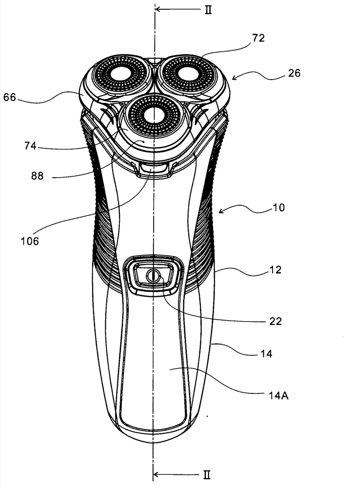
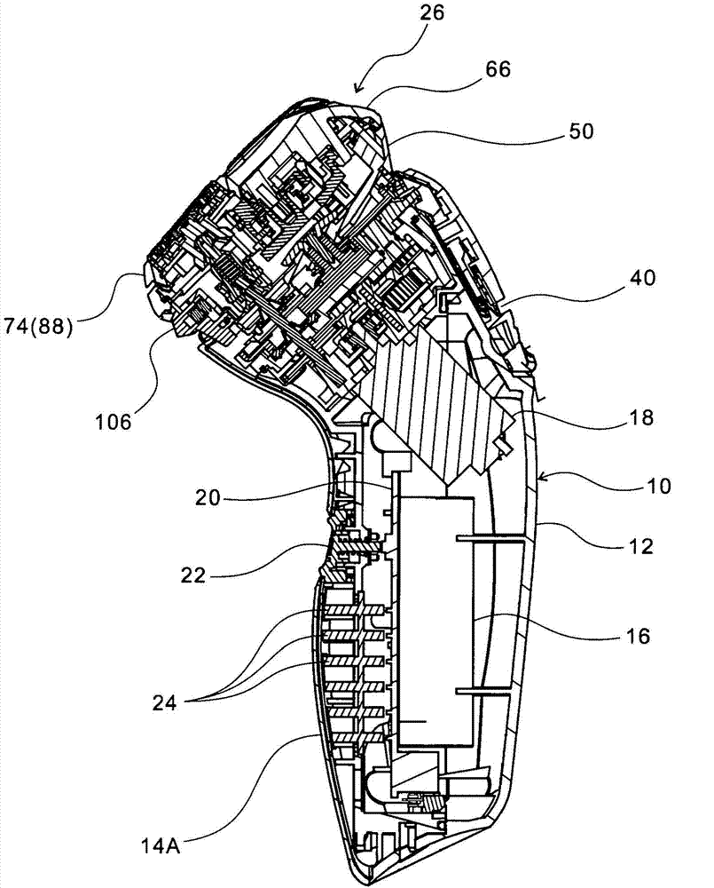
[0048] exist Figure 1~3 In the figure, reference numeral 10 is a main body part, and has a case 14 which bends the upper part of the substantially cylindrical handle part 12 obliquely forward and upward. The housing 14 is divided front and rear, such as figure 2 As shown, a rechargeable battery 16, an electric motor 18, a control circuit board 20, and the like are housed inside. A power switch 22 is installed on the front surface of the case 14. Below the switch 22, an LED lamp indicating the remaining charge of the battery 16, the operating state, etc., can be viewed from the outside through the translucent portion 14A of the case 14. 24 of the monitors.

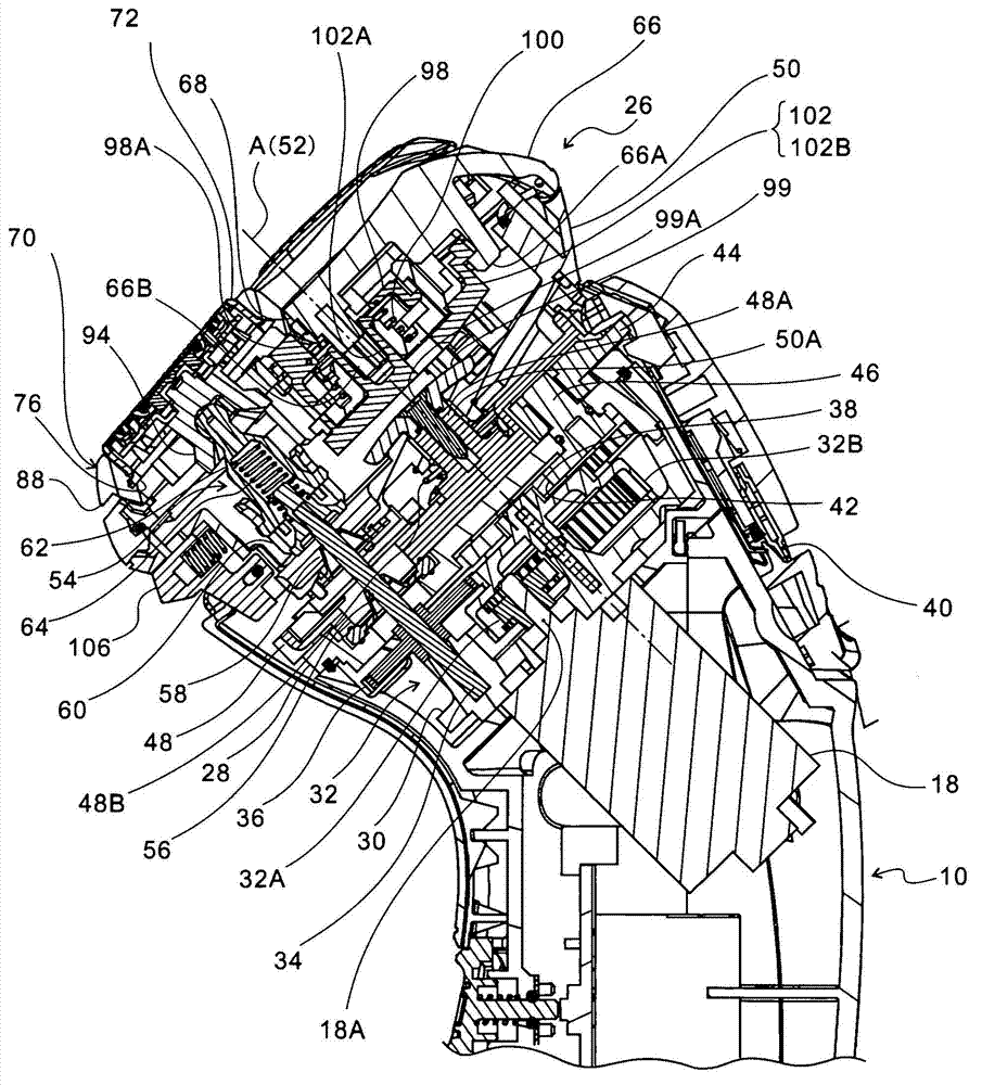
[0049] A head 26 is attached to the upper portion of the housing 14 in an openable, closable and detachable manner. In addition, the head 26 is inclined relative to the handle portion 12 of the housing 14 so that the shaving surface (the upper surface of the outer blade frame 66 described later) is directed obliquely f...


PUM


Abstract

A rotary electric shaver comprising: an outer cutter case (74) secured to the outer periphery of an outer cutter (72) and having a spherical sliding surface (82) formed on a lower portion of the outer periphery; an outer cutter case holder (78) which is fitted in a mounting port (68) to be vertically movable with an upper limit position thereof restrained and which pivotably holds the outer cutter case, guiding the spherical sliding surface of the outer cutter case (74); and a pushup plate (98) which imparts an upward return tendency to an outer cutter case assembly (70) formed of the outer cutter (72), the outer cutter case (74) and the outer cutter case holder (78). The outer periphery of the outer cutter case (74) is provided with a projection (88) which extends out to the upper surface of the outer cutter frame so as to serve as a stopper which prevents the outer cutter case (74) from sinking into the mounting port (68). This arrangement prevents the outer cutter from being caught by the inner edge of the mounting port of the outer cutter case. Shaving performance is improved with better closeness of the outer cutter to skin.

Description

technical field [0001] The present invention relates to an outer blade housing fixed on the outer periphery of the outer blade so that it can move up and down and swing in an outer blade frame held on the upper part of the main body, so that the inner blade comes into elastic contact with the outer blade from below to rotate. rotary electric shaver. Background technique [0002] In this type of electric shaver, when the substantially disk-shaped outer blade is pushed against the skin with a large pressing force, the outer blade sinks into the skin greatly, and there are excessively deep shaves or the outer periphery of the outer blade and the There is a possibility that the skin contact pressure is too high and the feeling of use may be deteriorated. Therefore, conventionally, it has been proposed to surround the outer periphery of the outer blade with an outer blade support ring (skin support ring) to prevent excessive contact pressure between the outer blade and the skin ...

Claims


Application Information

Patent Timeline
Patent Type & Authority Applications(China)
IPC IPC(8): B26B19/14
CPCB26B19/14B26B19/143B26B19/145
Inventor 小池秀明
Owner IZUMI PROD CO
Why Eureka
Try Eureka