Self-propelled trolley and self-propelled trolley conveying system

A self-propelled trolley and car body technology, applied in conveyors, mechanical conveyors, transportation and packaging, etc., can solve problems such as increasing system production costs, self-propelled trolleys cannot climb slopes, and system operating efficiency is reduced, achieving enhanced reliability Safety and security, flexible wiring, and cost-saving effects

Inactive Publication Date: 2013-07-17
HUBEI HUACHANGDA INTELLIGENT EQUIP
View PDF5 Cites 6 Cited by
  • Summary
  • Abstract
  • Description
  • Claims
  • Application Information

AI Technical Summary

Problems solved by technology

For example, the self-propelled trolley can only run on a horizontal track, and the climbing must be carried out with the help of auxiliary equipment such as chains, that is, the self-propelled trolley in the system cannot climb the slope with its own power
In the case where there is a level difference in the track, the system must add equipment such as elevators or chains to carry out the height difference of the workpiece, which increases the production cost of the system and reduces the operating efficiency of the system.

Method used


Image

  • Self-propelled trolley and self-propelled trolley conveying system
  • Self-propelled trolley and self-propelled trolley conveying system
  • Self-propelled trolley and self-propelled trolley conveying system

Examples


Embodiment 1

[0029] Embodiment 1: the self-propelled trolley with wheel structure

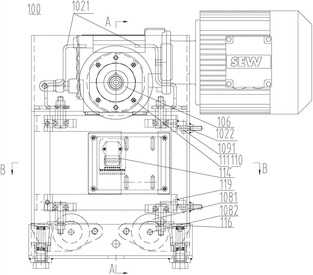
[0030] Please also see Figure 1 ~ Figure 4 , represents the self-propelled trolley structure of the embodiment of the present invention. The self-propelled trolley in this embodiment has a wheel structure, which can increase the driving friction of the climbing section of the track for the self-propelled trolley, thereby realizing the autonomous climbing of the self-propelled trolley. This wheel structure can be applied to both the main vehicle driven by power and the auxiliary vehicle without power drive. The main difference between the main vehicle and the auxiliary vehicle is whether to install a motor reducer. Without loss of generality, the following takes the main vehicle driven by power as an example to describe the wheel structure of the self-propelled trolley in detail.

[0031] Such as Figure 1 ~ Figure 4 As shown, one side of the track 200 is suspended on the auxiliary beam connected with th...

Embodiment 2

[0046] Embodiment 2: self-propelled trolley with variable section structure track

[0047] In the above embodiment, the driving friction of the self-propelled trolley 100 in the climbing section is increased by means of the idler wheels 108 , thereby realizing the autonomous climbing of the self-propelled trolley 100 . It is understood that excessive driving friction is detrimental to the track level.

[0048] Ideal situation: in the climbing section, the rollers 108 should be reliably close to the bottom surface of the climbing section of the track 200, so as to ensure the autonomous climbing of the self-propelled trolley 100; The bottom surface is automatically disengaged, so that the self-propelled trolley 100 can be guaranteed to have higher operating efficiency.

[0049] In this embodiment, the above-mentioned requirements can be realized by using the trigger device by the wheels. When the self-propelled trolley 100 is running in the horizontal section, the trigger devic...

Embodiment 3

[0055] Embodiment 3: self-propelled trolley with guiding mechanism

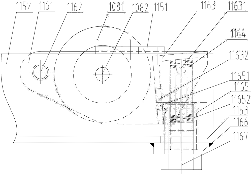
[0056] In the above-mentioned self-propelled trolley 100, the U-shaped groove 115 is used to carry the rollers 108 and the roller pressing mechanism 116, so that the relevant parts can be installed more conveniently, and its structure is very compact, which greatly reduces the space occupied by the parts. In addition, in this embodiment, the U-shaped groove 115 can also be used to install guide wheels 107 and other components, so as to further optimize the layout of equipment components, as follows.

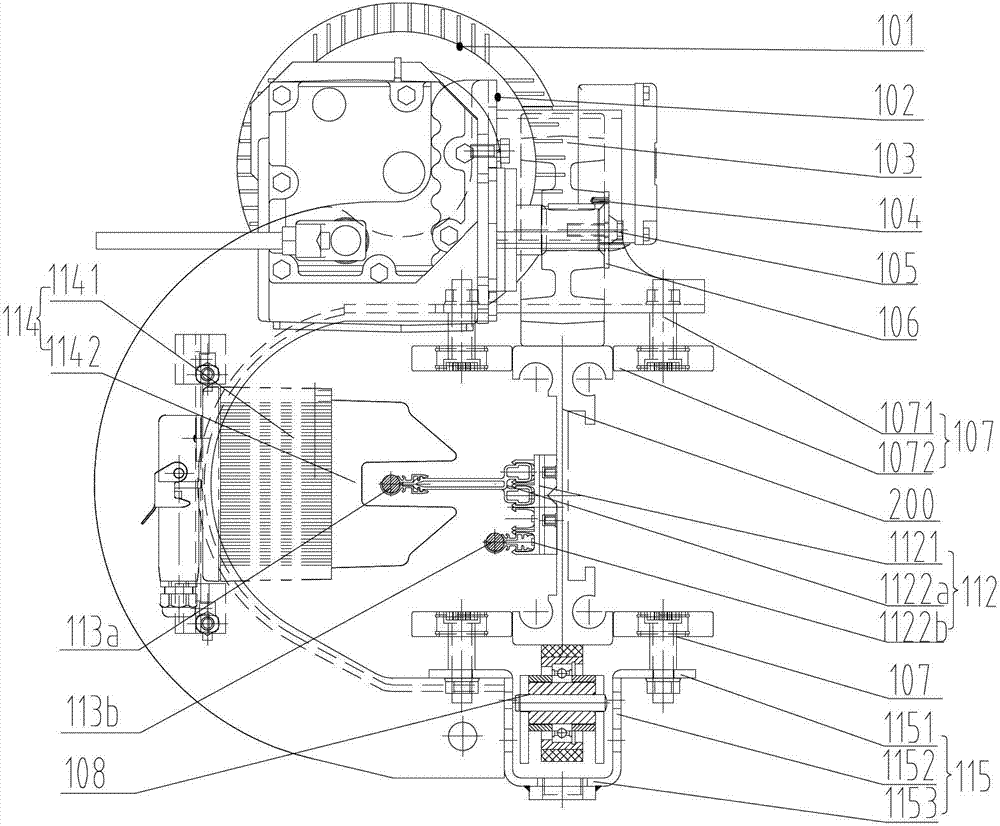
[0057] Such as image 3 As shown, the top of the U-shaped groove side wall 1152 is bent outwards to form two U-shaped groove flanges 1151, wherein the side wall and the flanges on one side are fixed on the end surface and the top surface of the lower opening of the car body 102, and Guide wheels 107 are all installed on the U-shaped groove flanging 1151 on both sides, and the axial direction of these guide whee...


PUM


Abstract

The invention relates to the field of conveying appliances and particularly discloses a self-propelled trolley and a self-propelled trolley conveying system. The self-propelled trolley comprises a trolley body with a lateral opening and a driving wheel arranged at an upper opening end of the trolley body, the driving wheel is carried on the top surface of a track to run, the self-propelled trolley further comprises a sustaining wheel and a sustaining wheel pressing mechanism, the sustaining wheel is installed at a lower opening end of the trolley body, and the sustaining wheel pressing mechanism drives the sustaining wheel to tightly adhere to the bottom surface of an uphill section of the track to run. The self-propelled trolley conveying system comprises the track and a plurality of self-propelled trolleys carried on the track to run. According to the self-propelled trolley, a sustaining wheel structure is arranged on the trolley body, the sustaining wheel can tightly adhere to the bottom surface of the uphill section of the track to run, thereby the driving friction force between the driving wheel and the track is increased, the self-propelled trolley can independently climb up without auxiliary equipment, and the system operating efficiency is increased.

Description

technical field [0001] The invention relates to the field of conveying equipment, in particular to a self-propelled trolley conveying system and its self-propelled trolley, which is mainly suitable for relatively high-strength rails made of aluminum alloy or other materials with a cross-section similar to "I". Running bicycle. Background technique [0002] Self-propelled trolley conveying system (hereinafter referred to as the system) is a common continuous conveying equipment, and its typical structure is mainly composed of rails, loading trolleys, trolley lines, electric chain hoists, electric turnouts, spreaders and other components. For the occasion of conveying lighter workpieces (generally no more than 3 tons), aluminum alloy rails with approximate "I" cross-sections are usually used, which are hung on the auxiliary beams through C-shaped connecting frames arranged at certain intervals; The trolley is generally composed of two or more wheels that run on the top surfac...

Claims


Application Information

Patent Timeline
Patent Type & Authority Applications(China)
IPC IPC(8): B65G35/00
Inventor 徐书军
Owner HUBEI HUACHANGDA INTELLIGENT EQUIP
Why Eureka
Try Eureka