Self-propelled trolley and self-propelled trolley conveying system
A self-propelled trolley and car body technology, applied in conveyors, mechanical conveyors, transportation and packaging, etc., can solve the problems that self-propelled trolleys cannot climb slopes, increase system production costs, and reduce system operating efficiency, so as to achieve enhanced reliability Safety and safety, cost saving, and the effect of improving conveying efficiency
- Summary
- Abstract
- Description
- Claims
- Application Information
AI Technical Summary
Problems solved by technology
Method used
Image
Examples
Embodiment 1
[0028] Embodiment 1: the self-propelled trolley with wheel structure
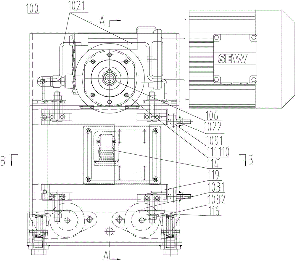
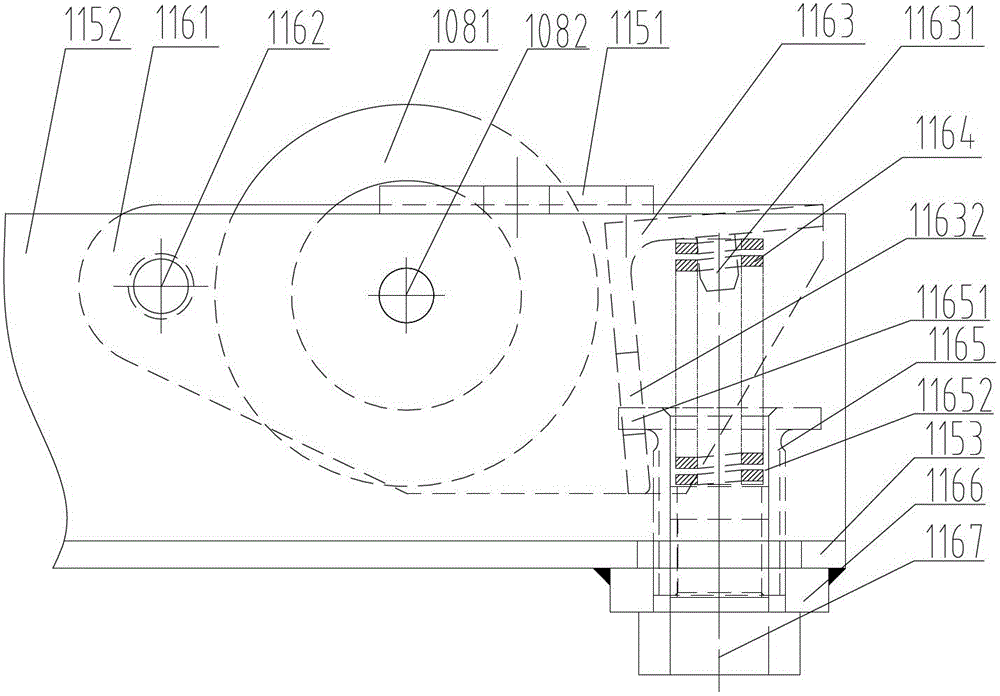
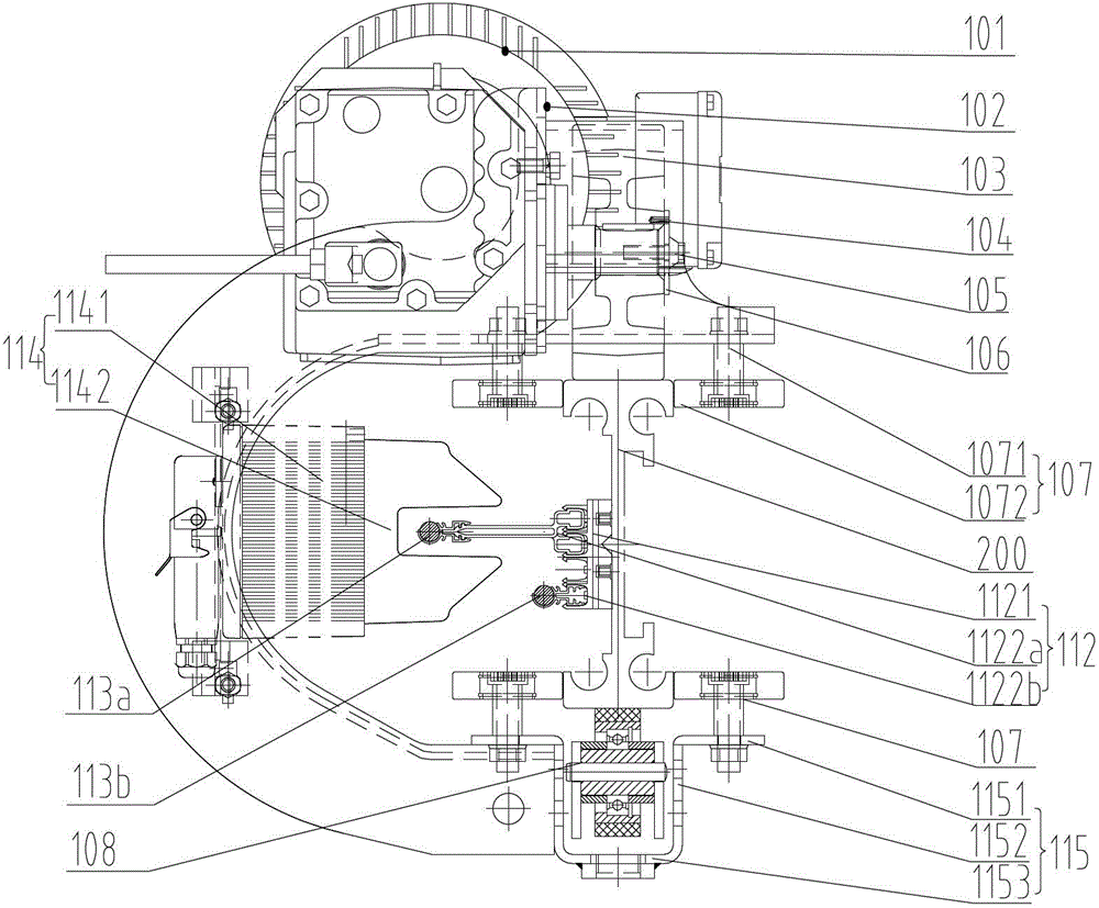
[0029] See also Figure 1 ~ Figure 4 , represents the self-propelled trolley structure of the embodiment of the present invention. The self-propelled trolley in this embodiment has a wheel structure, which can increase the driving friction of the climbing section of the track for the self-propelled trolley, thereby realizing the autonomous climbing of the self-propelled trolley. This wheel structure can be applied to both the main vehicle driven by power and the auxiliary vehicle without power drive. The main difference between the main vehicle and the auxiliary vehicle is whether to install a motor reducer. Without loss of generality, the following takes the main vehicle driven by power as an example to describe the wheel structure of the self-propelled trolley in detail.
[0030] Such as Figure 1 ~ Figure 4As shown, one side of the track 200 is suspended on the auxiliary beam connected with the steel ...
Embodiment 2
[0045] Embodiment 2: self-propelled trolley with variable section structure track
[0046] In the above embodiment, the driving friction of the self-propelled trolley 100 in the climbing section is increased by means of the idler wheels 108 , thereby realizing the autonomous climbing of the self-propelled trolley 100 . It is understood that excessive driving friction is detrimental to the track level.
[0047] Ideal situation: in the climbing section, the rollers 108 should be reliably close to the bottom surface of the climbing section of the track 200, so as to ensure the autonomous climbing of the self-propelled trolley 100; The bottom surface is automatically disengaged, so that the self-propelled trolley 100 can be guaranteed to have higher operating efficiency.
[0048] In this embodiment, the above-mentioned requirements can be realized by using the trigger device by the wheels. When the self-propelled trolley 100 is running in the horizontal section, the trigger devic...
Embodiment 3
[0054] Embodiment 3: self-propelled trolley with guiding mechanism
[0055] In the above-mentioned self-propelled trolley 100, the U-shaped groove 115 is used to carry the rollers 108 and the roller pressing mechanism 116, so that the relevant parts can be installed more conveniently, and its structure is very compact, which greatly reduces the space occupied by the parts. In addition, in this embodiment, the U-shaped groove 115 can also be used to install guide wheels 107 and other components, so as to further optimize the layout of equipment components, as follows.
[0056] Such as image 3 As shown, the top of the U-shaped groove side wall 1152 is bent outwards to form two U-shaped groove flanges 1151, wherein the side wall and the flanges on one side are fixed on the end surface and the top surface of the lower opening of the car body 102, and Guide wheels 107 are all installed on the U-shaped groove flanging 1151 on both sides, and the axial direction of these guide whee...
PUM
 Abstract
Description
Claims
Application Information
 - R&D
- Intellectual Property
- Life Sciences
- Materials
- Tech Scout
- Unparalleled Data Quality
- Higher Quality Content
- 60% Fewer Hallucinations
Browse by: Latest US Patents, China's latest patents, Technical Efficacy Thesaurus, Application Domain, Technology Topic, Popular Technical Reports.
© 2025 PatSnap. All rights reserved.Legal|Privacy policy|Modern Slavery Act Transparency Statement|Sitemap|About US| Contact US: help@patsnap.com


