Connecting structure of sliding-rail synchronous gears

A technology of connecting structure and synchronizing wheel, which is applied to lighting and heating equipment, supports, household appliances, etc., can solve the problem that the synchronous wheel and the connecting shaft cannot be guaranteed to rotate synchronously.

Active Publication Date: 2013-07-17
WUXI HAIDAER PRECISION SLIDES CO LTD
View PDF7 Cites 6 Cited by
  • Summary
  • Abstract
  • Description
  • Claims
  • Application Information

AI Technical Summary

Problems solved by technology

[0003] In view of the above problems, the present invention provides a connection structure of the synchronous wheel of the slide rail, which can solve the problem that the existing structure cannot guarantee the synchronous rotation of the synchronous wheel and the connecting shaft, and ensure that the drawer can slide smoothly

Method used


Image

  • Connecting structure of sliding-rail synchronous gears
  • Connecting structure of sliding-rail synchronous gears
  • Connecting structure of sliding-rail synchronous gears

Examples


Embodiment Construction

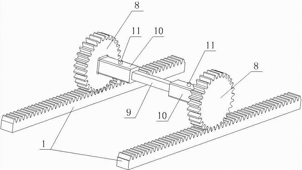
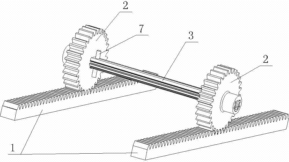
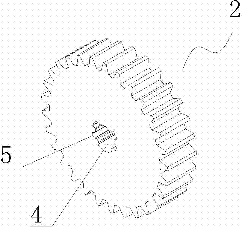
[0011] See figure 2 , image 3 and Figure 4 , the present invention includes two rack slide rails 1 installed in parallel, two synchronous gears 2 and a connecting shaft 3, and the two synchronous gears 2 are respectively installed on the two rack slide rails 1 and connected with the two rack slide rails 1 Toothed meshing connection, two synchronous gears 2 are connected by a connecting shaft 3, both synchronous gears 2 have a connecting shaft hole 4, the circumference of the connecting shaft hole 4 is provided with a toothed groove 5, and the connecting shaft 3 The outer peripheral surface is provided with positioning teeth 6 that match the toothed grooves 5 of the connecting shaft hole 4 , and the positioning teeth 6 of the connecting shaft 3 and the toothed grooves 5 of the connecting shaft hole 4 are directly gap-fitted. The two ends of the connecting shaft 3 are provided with radial through holes close to the mounting end of the synchronous gear 2, and a positioning p...


PUM


Abstract

The invention provides a connecting structure of sliding-rail synchronous gears, aiming to solve the problem that synchronous gears cannot be guaranteed to rotate with a connecting shaft synchronously in an existing structure and guaranteeing smooth sliding of a drawer. The connecting structure comprises two parallel mounted rack sliding rails, two synchronous gears and a connecting shaft. The two synchronous gears are mounted on the two rack sliding rails respectively and are connected with the two rack sliding rails in a teeth-shaped meshing manner. The two synchronous gears are connected through the connecting shaft. The connecting structure is characterized in that one connecting shaft hole is reserved on each synchronous gear, teeth-shaped grooves are reserved on the periphery of the connecting shaft holes, positioning teeth matched with the teeth-shaped grooves of the connecting shaft holes are arranged on the outer circumference of the connecting shaft, and the positioning teeth of the connecting shaft holes can be mounted with the teeth-shaped grooves of the connecting shaft in a clearance manner directly.

Description

technical field [0001] The invention relates to the field of slide rail structures for household appliances, in particular to the field of slide rail structures for large-capacity refrigerators, in particular to the connection structure of slide rail synchronous wheels. Background technique [0002] Generally, due to the large horizontal and horizontal spacing of large-capacity refrigerators, in order to ensure that the refrigerator drawer can be pulled smoothly, usually a synchronous slide rail mechanism is installed along the longitudinal pull direction at the horizontal and horizontal ends of the lower part of the drawer. The synchronous rack slide rail 1 installed in parallel direction, the two synchronous gears 8 installed in the drawer are meshed with the synchronous rack slide rail 1, see figure 1 A connecting shaft 9 is also installed between the two synchronous gears 8 to ensure that the gears 8 at both ends can be synchronously meshed and rotated on the respective ...

Claims


Application Information

Patent Timeline
Patent Type & Authority Applications(China)
IPC IPC(8): F25D25/02
Inventor 陆斌武
Owner WUXI HAIDAER PRECISION SLIDES CO LTD
Why Eureka
Try Eureka