
Conveying mechanism for 3D printer

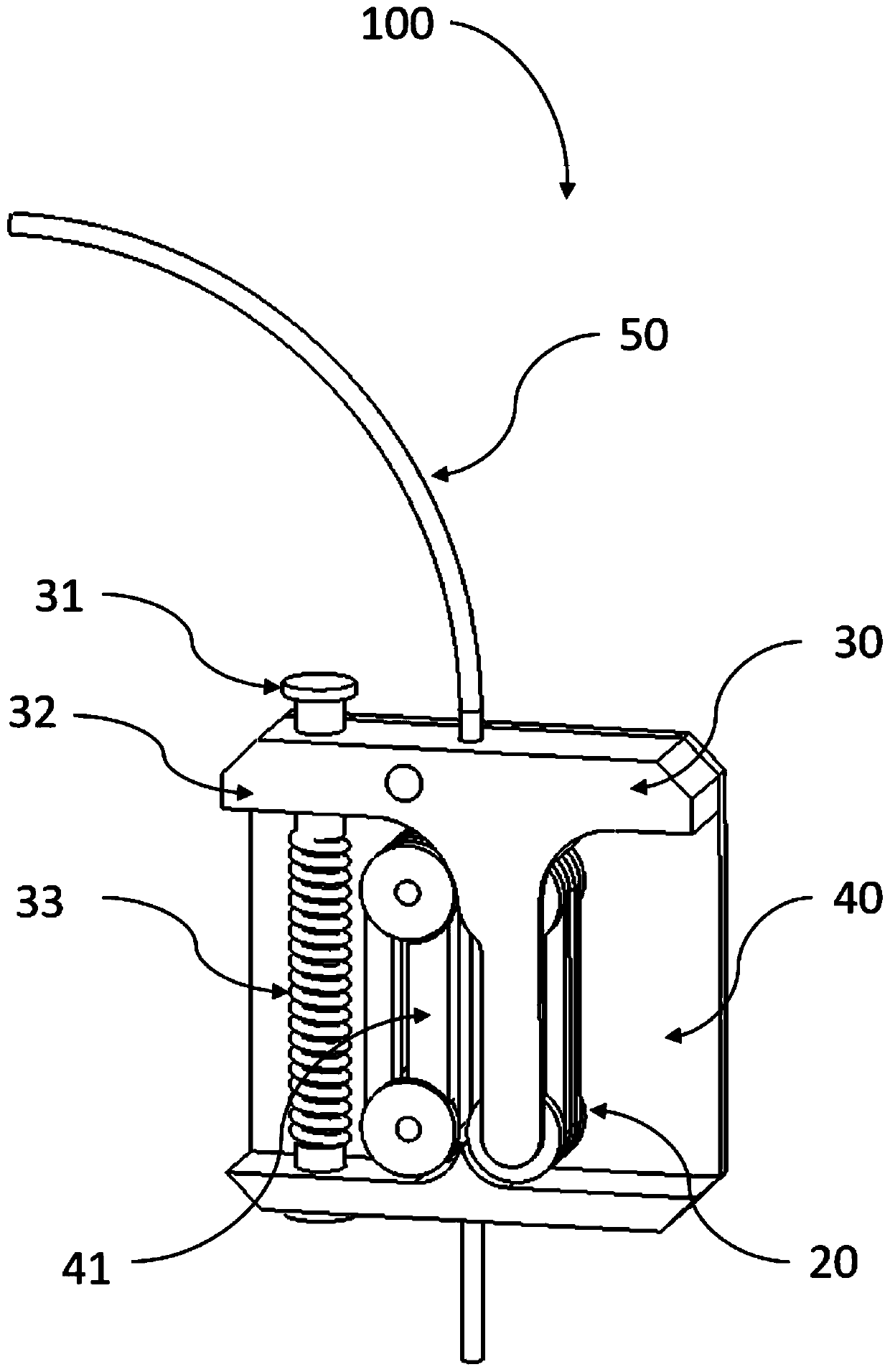
A 3D printer and feeding mechanism technology, applied in the field of 3D printing, can solve problems such as uneven extrusion force, gear wire damage, and feeding obstacles, so as to achieve stable extrusion force size and direction, reduce feeding obstacles, and reduce damage and damage Effect

Inactive Publication Date: 2019-12-27
XI AN JIAOTONG UNIV
View PDF8 Cites 2 Cited by
  • Summary
  • Abstract
  • Description
  • Claims
  • Application Information

AI Technical Summary

Problems solved by technology

Most of the existing feeding mechanisms use gears and guide wheels to transport the wires. During the feeding process, the gears will cause damage to the wires. If the clamping force on the brittle wires is too large, the wires will even be pinched off.
Moreover, the gear transmission is a point force, and there is a problem that the direction of the force on the wire is unstable and the extrusion force is uneven.
In addition, the use of gears to transport flexible wires is prone to material discounts, resulting in material feeding obstacles

Method used


Image

  • Conveying mechanism for 3D printer
  • Conveying mechanism for 3D printer

Examples


Embodiment Construction

[0028] In describing the present invention, it is to be understood that the terms "upper", "lower", "left", "right", "vertical", "horizontal", "top", "bottom", "inner", The orientation or positional relationship indicated by "outside", "one side", "one end", "one side", etc. are based on the orientation or positional relationship shown in the drawings, and are only for the convenience of describing the present invention and simplifying the description, rather than indicating or It should not be construed as limiting the invention by implying that a referenced device or element must have a particular orientation, be constructed, and operate in a particular orientation. In addition, the terms "first" and "second" are used for descriptive purposes only, and cannot be interpreted as indicating or implying relative importance or implicitly specifying the quantity of indicated technical features. Thus, a feature defined as "first" and "second" may explicitly or implicitly include on...


PUM


Abstract

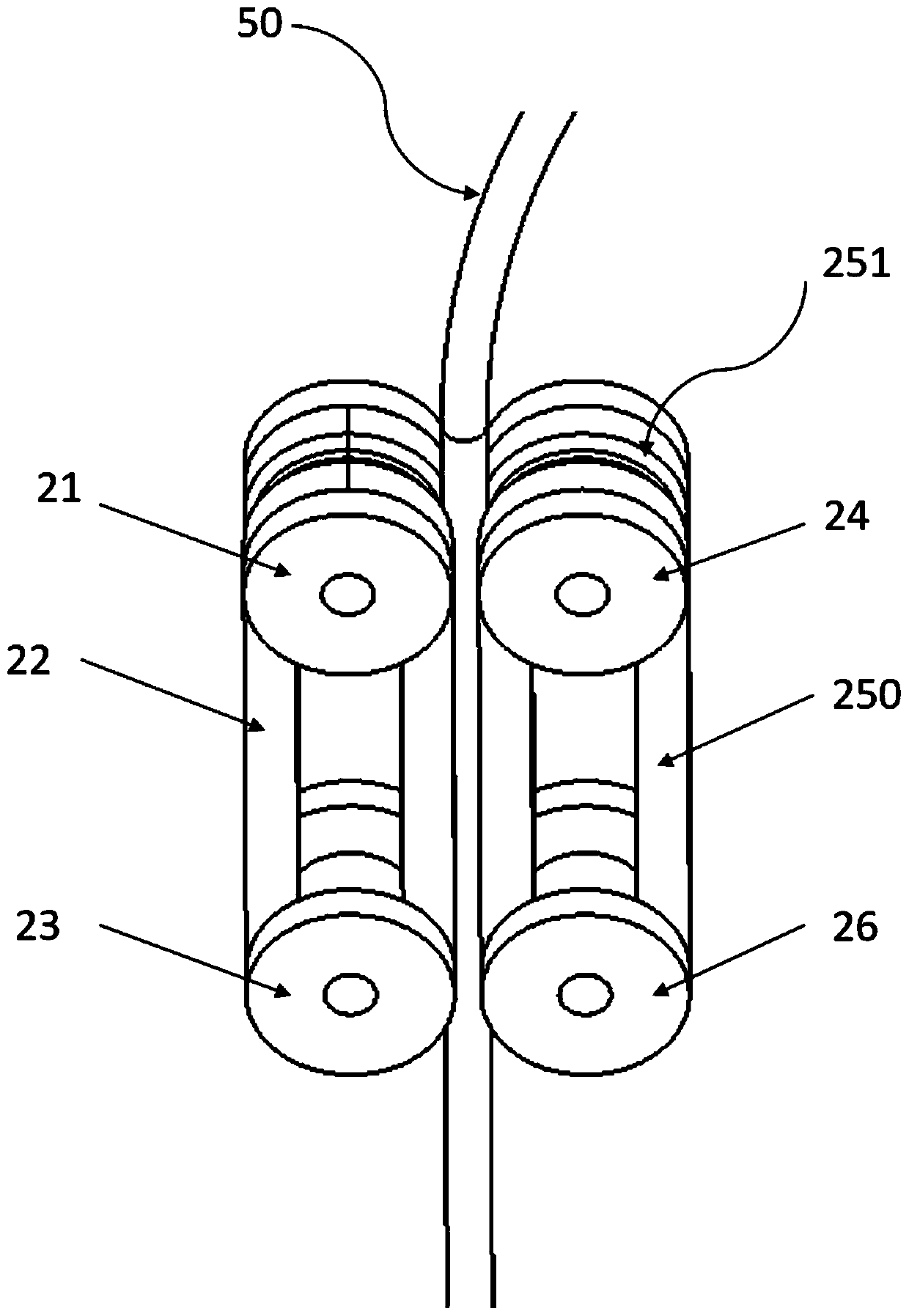
The invention discloses a conveying mechanism for a 3D printer. The conveying mechanism comprises a first mounting part and a second mounting part, a conveying structure is arranged between the firstmounting part and the second mounting part, a driving part of the conveying structure is mounted on the first mounting part, a driven part of the conveying structure is mounted on the second mountingpart, the second mounting part can rotate relative to the first mounting part, and wire materials are arranged between the driving part and the driven part and conveyed through friction force. According to the conveying mechanism, the wire materials are clamped through a driving belt and a driven belt, the materials are conveyed through the friction force, and destroy and damage to the wire materials are reduced while stable conveying of the wire materials is ensured; guiding is conducted through a guiding groove, and the magnitude and direction of extrusion force are stable; and the guiding groove can achieve the effect of straightening the materials, and the problem of a conveying obstacle caused by wire material folds is reduced.

Description

technical field [0001] The invention belongs to the technical field of 3D printing, and in particular relates to a feeding mechanism for a 3D printer. Background technique [0002] Additive manufacturing technology, also known as rapid prototyping and 3D printing technology, is a manufacturing technology based on layer-by-layer accumulation of materials. 3D printing technology can realize the rapid prototyping of products with complex geometric shapes, which greatly makes up for the shortcomings of traditional machining methods. In recent years, with the continuous development and maturity of 3D printing technology, 3D printing products have been used in aerospace, industrial , education, product design and other fields. [0003] At present, the coiled round wire is the most common 3D printing material on the market. The wire is conveyed through the feeding mechanism of the 3D printer, enters the heating nozzle to be heated to a molten state, and finally extrudes from the n...

Claims


Application Information

Patent Timeline
IPC IPC(8): B29C64/321B33Y40/00
CPCB33Y40/00B29C64/321
Inventor 王玲单存清汤磊李涤尘
Owner XI AN JIAOTONG UNIV
Learn More