Wax column forming equipment

A molding equipment and wax column technology, applied in the field of wax column molding equipment, can solve the problems of high labor intensity, low processing efficiency, troublesome operation, etc., and achieve the effect of low labor intensity, high processing efficiency and simple operation

Pending Publication Date: 2020-01-17
青岛欧亚自动化设备有限公司
View PDF7 Cites 2 Cited by
  • Summary
  • Abstract
  • Description
  • Claims
  • Application Information

AI Technical Summary

Problems solved by technology

[0004] However, at present, when using this method to manually process the wax column, the operation is more troublesome, the labor intensity is high, and the processing efficiency is low.

Method used


Image

  • Wax column forming equipment
  • Wax column forming equipment
  • Wax column forming equipment

Examples


Embodiment 1

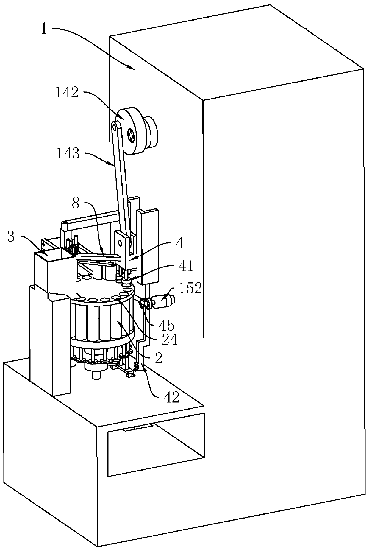
[0043] Embodiment one: refer to figure 1 , is a kind of wax column molding equipment disclosed by the present invention, which includes a frame 1, and the middle part of the frame 1 is provided with a rotating body 2 whose axis is vertically arranged.

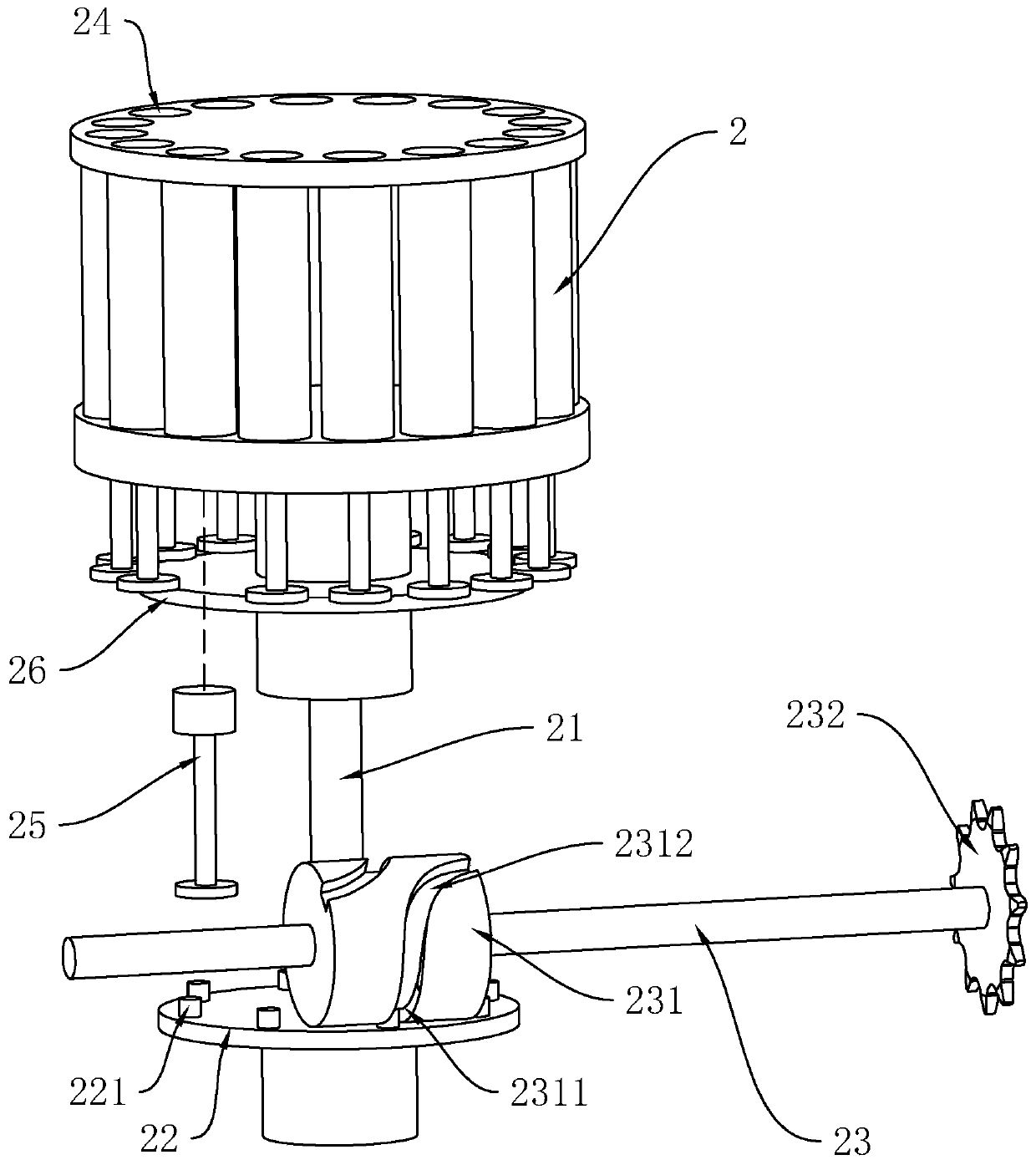
[0044] refer to figure 2 A rotating shaft 21 is fixedly connected to the axial position of the rotating body 2, and the rotating shaft 21 is rotatably connected to the frame 1 (not shown in the figure). The lower end of the rotating shaft 21 is fixedly connected with a turntable 22 coaxial with the rotating shaft 21 , and the upper side of the turntable 22 is centered on the center of the turntable 22 with a number of indexing columns 221 rotatably connected to the turntable 22 , and the frame 1 corresponds to the turntable 22 The position on the upper side is rotatably connected with the transmission shaft four 23 arranged horizontally on the axis, and the middle part of the transmission shaft four 23 is fixedly connected wi...

Embodiment 2

[0058] Embodiment two: refer to Figure 6 , a kind of wax column forming equipment, compared with the first embodiment, the difference is that the transmission shaft two 14 includes a first half shaft 146 and a second half shaft 147 that are respectively rotatably connected to the frame 1 and are coaxial, and the sprocket four 141 is affixed to the first semi-shaft 146, sprocket five 144 and eccentric wheel one 142 are affixed to the second semi-shaft 147, and one end of the second semi-shaft 147 and the first semi-shaft 146 close to each other is provided with a device that can be connected to the second half-shaft under normal conditions. Friction clutch 148 between half shaft 146 and second half shaft 147 .

[0059] Compared with Embodiment 1, the advantage is that: under normal conditions, the friction clutch 148 is used to complete the connection between the first half shaft 146 and the second half shaft 147, thereby ensuring the synchronous rotation of the first half sha...


PUM


Abstract

Wax column forming equipment comprises a rack, a rotating body is rotatably connected to the middle of the rack, a plurality of through grooves are evenly formed in the upper surface of the rotating body, and ejection columns are slidably connected to the lower ends of the through grooves; a hopper is fixedly connected above the rack corresponding to the rotating body; a pressing column capable ofbeing inserted into the through groove is arranged at a position, corresponding to one side of the hopper, of the rack. A push rod capable of pushing the corresponding ejection column to move upwardsis arranged at the position, corresponding to the lower side of the pressing column, of the rack. An ejection rod capable of pushing the ejection column to push the wax column in the through groove out of the upper side of the through groove is arranged at the position, corresponding to one side of the push rod, of the rack, a discharging conveying belt is arranged at the position, correspondingto one side of the rotating body, of the rack, and a swing plate capable of pushing the wax column on the upper side of the through groove to the discharging conveying belt is further arranged on therack; the rack is further provided with an inserting rod capable of being inserted into the through groove in the vertical direction to push the jacking column to reset. The wax column forming equipment has the advantages of being easy to operate, low in labor intensity and high in machining efficiency.

Description

technical field [0001] The invention relates to the technical field of wax column processing, in particular to a wax column forming equipment. Background technique [0002] Wax is an oil produced by animals, plants or minerals. It is solid at room temperature, has plasticity, is easy to melt, insoluble in water, and soluble in carbon disulfide and benzene. Wax is a mixture of several higher alkanes, mainly n-docosane and n-octadecane, containing about 85% carbon elements and about 14% hydrogen elements. There is no single chemical element symbol. [0003] When the existing wax column is made, the wax powder that has been mixed and processed is usually manually packed into a cylindrical container, and then a pressure device such as a plug is used to apply pressure to the wax powder in the cylindrical container, so that the wax powder Extruding the wax column, and then taking the wax column out of the cylindrical container, the cold pressing of the wax column can be completed...

Claims


Application Information

Patent Timeline
Patent Type & Authority Applications(China)
IPC IPC(8): C11C5/02
CPCC11C5/021
Inventor 任志法任博闻卢深海任志才
Owner 青岛欧亚自动化设备有限公司
Why Eureka
Try Eureka