
Two-way metal hard-sealed floating ball valve

A floating ball valve and hard seal technology, applied in valve details, valve devices, valve housing structure, etc., can solve the problems of upstream pipeline equipment and personnel safety hazards, cost increase, complicated operation, etc., and achieve simplified operation complexity and reliability Guaranteed and cost-reducing effects

Active Publication Date: 2015-05-20
XINUOWEI VALVE CONTROL SUZHOU CO LTD
View PDF5 Cites 0 Cited by
  • Summary
  • Abstract
  • Description
  • Claims
  • Application Information

AI Technical Summary

Problems solved by technology

[0004] The common hard-sealed floating ball valve is a one-way seal. When the valve is installed to the closed state of the pipeline, it can only achieve downstream side sealing. When the downstream pressure of the medium increases due to temperature changes, the phenomenon of medium backflow will occur, which has strict requirements. A separate check valve will be added to ensure the reverse flow of the medium, resulting in increased cost and complicated operation, but no check valve will also bring great safety hazards to upstream pipeline equipment and personnel

Method used


Image

  • Two-way metal hard-sealed floating ball valve
  • Two-way metal hard-sealed floating ball valve

Examples


Embodiment Construction

[0017] The specific embodiments of the present invention will be described in further detail below in conjunction with the drawings and embodiments. The following examples are used to illustrate the present invention, but not to limit the scope of the present invention.

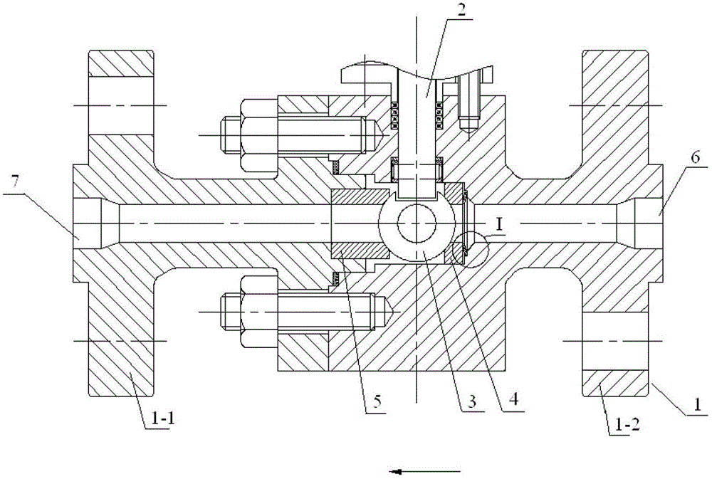
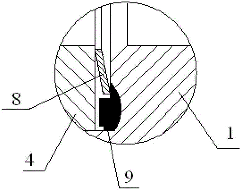
[0018] figure 1 It is a schematic structural diagram of a two-way metal hard-seal floating ball valve according to an embodiment of the present invention; figure 2 Yes figure 1 Partial enlarged view of "Ι" in the middle. Reference Figure 1~2 The ball valve includes: a valve body 1, a valve stem 2, a ball 3, an upstream valve seat 4 and a downstream valve seat 5. The valve body 1 is provided with an inlet 6 and an outlet 7, and the inlet 6 and the outlet 7 are mutually Connected, the upstream valve seat 4 is provided with a disc spring 8 on the end face close to the inlet 6, and the disc spring 8 is located between the upstream valve seat 4 and the valve body 1. The valve body 1 is provided with a sealing tab...


PUM


Abstract

The invention discloses a two-way metal hard-sealed floating ball valve, and relates to the technical field of ball valve designs. The ball valve comprises a valve body, a valve rod, a ball body, an upstream valve seat and a downstream valve seat, wherein the valve body is provided with an inlet and an outlet, which are communicated; a Belleville spring is arranged on an end face, close to the inlet, on the upstream valve seat, and is positioned between the upstream valve seat and the valve body; and a sealing stage is arranged in the valve body, and is at a preset distance away from the upstream valve seat. According to the hard-sealed floating ball valve capable of realizing two-way sealing, the cost is lowered, and complexity in operation is reduced; in addition, the sealing of the ball valve in a flow direction is ensured, the ball valve can be sealed in a reverse direction, and the requirements of sealing in a high-pressure state and a low-pressure state can be met; and the sealing stage is arranged, so that the reverse sealing reliability can be effectively ensured.

Description

Technical field [0001] The invention relates to the technical field of ball valve design, in particular to a two-way metal hard-seal floating ball valve. Background technique [0002] The ball valve is defined in the standard GB / T21465-2008 "Valve Terminology" as a valve in which the opening and closing part (sphere) is driven by the stem and rotates around the axis of the stem. It is mainly used to cut off or connect the medium in the pipeline, and can also be used for fluid adjustment and control. [0003] Ball valves are classified into soft-sealed ball valves and hard-sealed ball valves according to the sealing principle and sealing surface materials. Among them, the ball and valve seat of the metal hard-seal floating ball valve completely adopt a metal-to-metal sealing method. [0004] The common hard-sealed floating ball valve is a one-way seal. When the valve is installed to the pipeline in a closed state, only the downstream side can be sealed. When the pressure of the down...

Claims


Application Information

Patent Timeline
Patent Type & Authority Patents(China)
IPC IPC(8): F16K5/20F16K27/06
Inventor 韩泽海李麦
Owner XINUOWEI VALVE CONTROL SUZHOU CO LTD
Learn More