Seal valve gum cover for direct-acting valve

A sealing valve, direct-acting technology, applied in the direction of shaft seal, valve details, valve device, etc., can solve the problems of low longitudinal bearing pressure of rubber cylindrical valve sleeve, weakening bearing pressure of rubber seal, small high pressure bearing capacity, etc., to achieve Resistant to wave peak high pressure impact, increased longitudinal pressure, and good sealing performance

Active Publication Date: 2014-12-17
JIANGSU FEIYUE PUMP GRP
View PDF9 Cites 0 Cited by
  • Summary
  • Abstract
  • Description
  • Claims
  • Application Information

AI Technical Summary

Problems solved by technology

However, for the control of high-pressure fluid medium valves and the application of ultra-high pressure valves, it seems powerless and incompetent
This is mainly due to the small high-pressure bearing capacity of the rubber cylindrical valve sleeve and sealing sleeve of the sealing part. Although increasing the hardness of the rubber can also increase the mechanical strength to a limited extent, and reduce the one-way gap pressure of the rubber seal by reducing the inner diameter of the limit ring as much as possible. The purpose of weakening the pressure of the rubber seal is obtained by reducing the area, but it is generally only suitable for use in the range of low fluid medium pressure. In practical applications, under the influence of large tap water pressure fluctuations or water hammer pressure, the local gap surface of the rubber seal material It is easy to expand and become thinner or even burst, and the longitudinal bearing pressure of the rubber cylindrical valve sleeve is low, thus shortening the service life of the valve

Method used


Image

  • Seal valve gum cover for direct-acting valve
  • Seal valve gum cover for direct-acting valve

Examples


Embodiment Construction

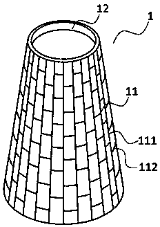
[0015] Such as figure 1 As shown, the sealing valve rubber sleeve 1 of the present invention is in the shape of a cone, that is, a trumpet-shaped rubber sealing sleeve with a large diameter at one end and a small diameter at the other end. The rubber sleeve body is lined with mesh inner ribs 11. A protruding ring 12 connected with it is provided on the periphery of the end. The body of the rubber sleeve is made of rubber material (such as silicone rubber, fluorine rubber, etc.), and the mesh inner rib is made of polyester, nylon or rigid wire. The transverse ribs 112 of the netted inner ribs have a certain degree of stretchability, and are arranged in a staggered manner between the longitudinal ribs 111 . The length of the longitudinal rib (the direction of the reciprocating movement of the valve stem when the valve is opened and closed) is a certain amount and cannot be stretched. When the present invention works in a direct-acting valve, there is only constant varicose res...


PUM


Abstract

The invention relates to a seal valve gum cover for a direct-acting valve. The seal valve gum cover for the direct-acting valve comprises a gum cover body which is in a pyramidal shape. A net-shaped inner rib is lined inside the gum cover body. The gum cover body is made of rubber materials. The inner rib is made of fiber materials such as dacron and nylon or rigid metal wires. Transverse ribs of the net-shaped inner rib have flexibility and are arranged among longitudinal ribs in a staggered mode. A layer of the net-shaped inner rib is lined on a film face of the seal valve gum cover, the transverse ribs of the net-shaped inner rib can be flexible in a limited mode, the longitudinal ribs of the net-shaped inner rib can not be flexible, the longitudinal tension force of the seal valve gum cover is increased, longitudinal mechanical tension force intensity is improved, the longitudinal bearing pressure of the seal valve gum cover in the direct-acting valve is increased greatly, and at the same time, the transverse ribs of the seal valve gum cover can be flexible in the free limited mode. The pyramidal seal valve gun cover can reduce an annular interval face between a protrusive loop and a valve rod, and accordingly the bearing pressure of the annular interval face can be reduced. Not only is corresponding tightness on the edge of periphery surface of a valve opening of the valve rod ensured, but also convenience in production and assembly can be ensured.

Description

technical field [0001] The invention relates to a valve used in a liquid pipeline, in particular to a component used in a direct-acting valve (or called a rubber sleeve valve). Background technique [0002] In the existing valves, the valve core is subject to the influence of water pressure or air pressure. The greater the water or air pressure, the greater the pressure of water or air on the valve core, so that the resistance of the valve core to open or close is also lower. will increase accordingly. Therefore, the force applied when opening or closing will also be great. This causes increased wear on the spool and causes leakage, shortening service life. [0003] Chinese patent CN1012696736A discloses a valve, which includes a valve body, a valve stem, an input port and an output port. The valve stem is a hollow body, and a through hole is arranged on the valve stem. A sealing sleeve is arranged between the valve stem and the upper limit ring. The upper edge of the sea...

Claims


Application Information

Patent Timeline
Patent Type & Authority Patents(China)
IPC IPC(8): F16K41/10
Inventor 夏育红
Owner JIANGSU FEIYUE PUMP GRP
Why Eureka
Try Eureka