
Automatic tripping device and tripping method for magnetic hook

A technology of automatic tripping and tripping device, applied in the direction of fixtures, generators/motors, electrical components, etc., can solve the problems of ease of operation, poor versatility and applicability, and achieve good versatility, convenient operation, and adhesion. Strength boosting effect

Active Publication Date: 2015-08-19
惠州市鼎盛磁业有限公司
View PDF7 Cites 0 Cited by
  • Summary
  • Abstract
  • Description
  • Claims
  • Application Information

AI Technical Summary

Problems solved by technology

[0005] The technical problem to be solved by the present invention is that the magnetic buckle structure in the prior art is relatively poor in operation convenience, versatility and applicability, and a magnetic buckle with good operation convenience, versatility and applicability is provided. Buckle device and corresponding tripping method

Method used


Image

  • Automatic tripping device and tripping method for magnetic hook
  • Automatic tripping device and tripping method for magnetic hook
  • Automatic tripping device and tripping method for magnetic hook

Examples


Embodiment 1

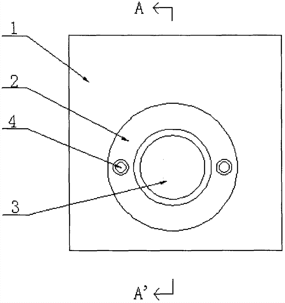
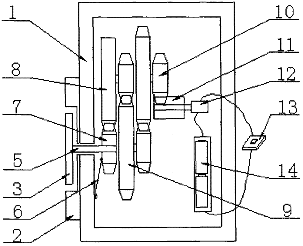
[0045] Such as Figure 1-5 Shown is a preferred embodiment of the present invention. This embodiment is an automatic tripping device and a tripping method for magnetic buckle, which are used to adhere and detach the first object 1 and the second object 15.

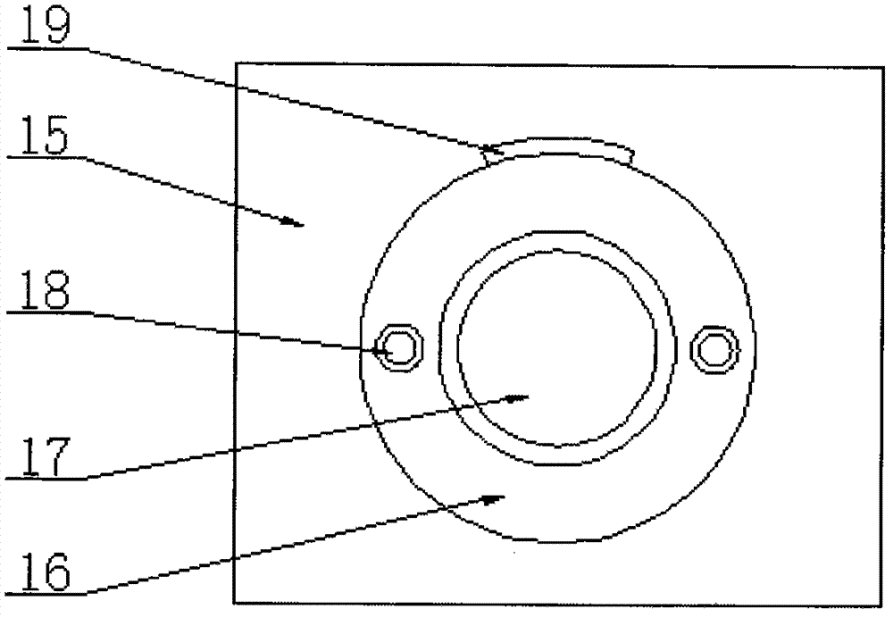
[0046] The first object 1 includes a first conductive disk 2, a first magnetic sheet 3, a transmission rod 5, a deceleration device, a return spring 6, a motor 12, a switch 13 and a battery box 14. The second object 15 includes a second conductive disk 16 and a second magnetic sheet 17.

[0047] The second magnetic sheet 17 is fixedly arranged on the outer surface of the second object 15, and the second magnetic sheet 17 is a circular multi-pole magnetic sheet. Such as Figure 4 As shown, in this embodiment, the magnetic poles of the second magnetic sheet 17 are eight poles. Further, the second magnetic sheet 17 is a circular multi-pole axially magnetized magnetic sheet.

[0048] The first magnetic sheet 3 is arranged on the ou...

Embodiment 2

[0061] Such as Figure 6-7 Shown is another embodiment of the present invention.

[0062] Different from the first embodiment, in this embodiment, the magnetic poles of the second magnetic sheet 17 and the first magnetic sheet 3 are quadruple. Correspondingly, the gear teeth of the gears of the first reduction gear set 8 and the transmission wheel 7 occupy 1 / 4 of the entire circumference.

[0063] In other embodiments, the magnetic poles of the second magnetic sheet 17 and the first magnetic sheet 3 may also be six poles, ten poles or others. Correspondingly, the first reduction gear set 8 and the transmission The gear teeth of the gear matched with the wheel 7 occupy 1 / 6, 1 / 10 or other of the entire circumference. The change of this data does not affect the purpose of the present invention.

[0064] In other embodiments, the positions of the groove 4 and the protrusion 18 can be exchanged, and this change does not affect the purpose of the invention.

[0065] In other embodiments,...


PUM


Abstract

The invention provides an automatic tripping device and tripping method for a magnetic hook. A second magnetic sheet is fixed on the outer surface of a second object. The second magnetic sheet is a round multi-pole magnetic sheet. A first magnetic sheet is arranged on the outer surface of a first object. The first magnetic sheet is a round multi-pole magnetic sheet which is identical to the second magnetic sheet. A transmission rod is fixed at a side, facing the first object, of the central position of the first magnetic sheet. The first magnetic sheet is suitable for rotating around the center of the first magnetic pole. The transmission rod is connected to a power output terminal of an electric motor through a reduction device. The electric motor is connected with a switch and a battery box through leads. The switch controls the switching-on and the switching-off of a circuit. According to the invention, the tripling device and method for the magnetic hook is good in operation convenience, universality and adaptability.

Description

Technical field [0001] The invention relates to the technical field of connection devices and equipment, in particular to a magnetic buckle automatic trip device and a trip method. Background technique [0002] In today's society, magnetic buckles are inseparable from people’s daily life. Schoolbags, shoes, clothes, doors and windows are increasingly using magnetic buckles as a connection method. Magnetic buckles have high adhesion and convenient release. The characteristics are closely watched by everyone. As we all know, the greater the magnetic force of the magnetic buckle, the greater its adhesion force, and the greater the difficulty of tripping; on the contrary, the smaller the magnetic force of the magnetic buckle, the smaller its adhesion force, and the less difficult the tripping. Therefore, the adhesive force of the magnetic buckle and the convenience of tripping are contradictory. [0003] In order to solve this contradiction and make the magnetic buckle reduce the dif...

Claims


Application Information

Patent Timeline
Patent Type & Authority Applications(China)
IPC IPC(8): H02N11/00
CPCF16B1/00F16B2200/83
Inventor 潘君昂叶青
Owner 惠州市鼎盛磁业有限公司
Learn More