Electric connector

A technology of electrical connectors and paired connectors, applied in connection, fixed connection, circuits, etc., can solve the problems of high-frequency performance degradation of electrical signals, and achieve the effect of easy impedance control and no degradation of high-frequency performance

Inactive Publication Date: 2013-07-24
SMK CO LTD
View PDF5 Cites 3 Cited by
  • Summary
  • Abstract
  • Description
  • Claims
  • Application Information

AI Technical Summary

Problems solved by technology

That is, the impedance control performed on the connection portion 23 and the wiring of the circuit board is not performed on the contact portion 22, and therefore, the degradation of the high-frequency performance of the electrical signal may occur at the contact point 20 of the electrical connector A.

Method used


Image

  • Electric connector
  • Electric connector
  • Electric connector

Examples


Embodiment Construction

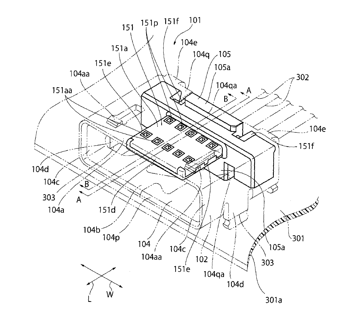
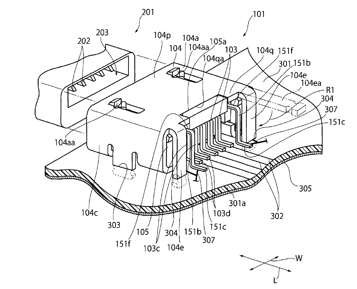
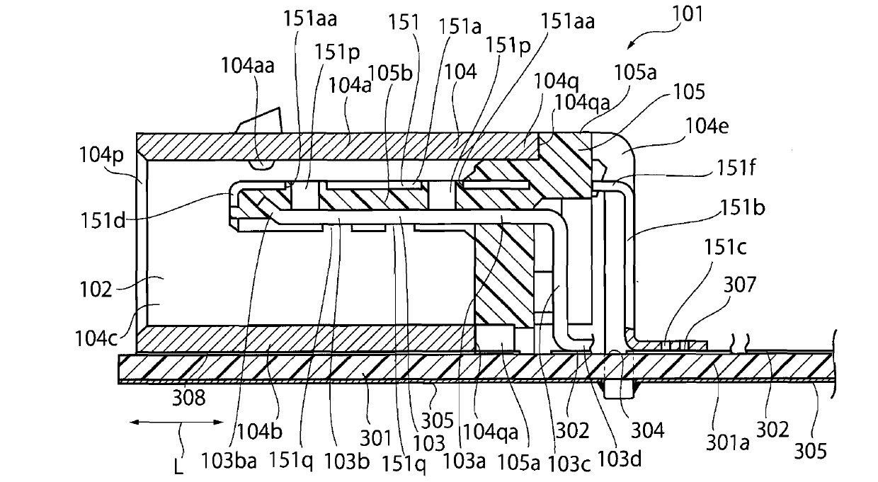
[0020] Below, based on Figure 1 to Figure 8 One way of implementing is described. figure 1 It is a perspective view of the electrical connector 101 viewed from the upper front side. figure 2 It is a perspective view of the electrical connector 101 viewed from the upper rear side. image 3 is a side sectional view of the electrical connector 101 . The electrical connector 101 has a shielding member 104 and a cover 105 (their structures will be described in detail later), is formed with a mounting portion 102 capable of mounting the mating connector 201 , and is mounted on the upper surface of the circuit board 301 . The electrical connector 101 has a plurality (five in this embodiment) of contact members 103 . The plurality of contact members 103 are connected to the wiring 302 on the upper surface of a plate-shaped base material 301 a constituting the circuit board 301 . When the mating connector 201 is mounted on the mounting portion 102 of the electrical connector 101 ...


PUM


Abstract

The invention relates to an electric connector. Even when the electric connector is installed on a circuit board, high frequency performance of electric signals is not degraded. A matched connector is installed on an installation part (102) of the electric connector (101). A shade (105) is formed by shaping an insulating resin and is provided with an extending part embedded with an embedding hole of the matched connector when being installed on the installation part. A contact part (103b) of a contact component (103) is contacted with a contact component on a matched side in the embedding hole of the matched connector when being installed on the installation part and is arranged in list on the lower surface of the extending part (105b). A metal piece (151) is fixed on the shade and is grounded through a grounding part (151c). A flat part (151a) arranged on the metal piece is arranged on the upper surface of the extending part and is in parallel with the list of the contact parts (103b) of the contact component.

Description

technical field [0001] The present invention relates to an electrical connector mounted on a circuit board and mated with a mating connector for transmitting electrical signals. Background technique [0002] In paragraphs 0010, 0014, 0018 and 0019 of Patent Document 1, it is recorded as follows: "In figure 1 and figure 2 Among them, the electrical connector assembly 1 has an electrical connector A mounted on a circuit board (not shown), and a mating connector B fitted with the electrical connector A. Here, electrical connector A such as Figure 1 to Figure 5 As shown, there are a cover 10 , a plurality of contacts 20 attached to the cover 10 , and a metal cover 30 attached to the cover 10 . ”, “On the main body portion 11 of the cover 10, the metal plate 40 formed to cover the upper surface 12b and the side surfaces 12c of the protective wall 12 is fixed. The metal plate 40 has an upper plate portion 41 fixed on the main body portion 11 and covering the upper surface 12...

Claims


Application Information

Patent Timeline
Patent Type & Authority Applications(China)
IPC IPC(8): H01R13/6474H01R13/648H01R13/02H01R12/51
Inventor 小野直之林攻
Owner SMK CO LTD
Why Eureka
Try Eureka