
Connector

A technology for connectors and contact surfaces, applied in the direction of connection, parts of connection devices, coupling devices, etc., can solve problems such as damage, cracking of insulating resin parts, and restrictions, and achieve the effects of damage suppression and easy control

Inactive Publication Date: 2019-07-05
SMK CO LTD
View PDF1 Cites 0 Cited by
  • Summary
  • Abstract
  • Description
  • Claims
  • Application Information

AI Technical Summary

Problems solved by technology

[0008] However, in the above-mentioned general prior art connector, since the plurality of signal terminals and ground terminals are all formed by parts of the same shape in which the conductor plate is bent, and these are arranged side by side, Therefore, the degree of freedom in the design of connectors that want to expand the width or arrangement pitch of multiple terminals (wiring patterns on the mounting board side) is limited.
Therefore, in addition to the difficulty in controlling the impedance of the signal terminals, there is also a problem that the size of the product will be increased.
[0009] Moreover, in the connector of the prior art, since it becomes the configuration that a plurality of signal terminals and ground terminals of the same shape are inserted side by side with respect to the insulating resin part of the connector housing, therefore, all the terminals of the insulating resin part are The stress caused by the insertion of the plug acts in the same direction, and there is a possibility of damage such as cracking at the insulating resin part.
[0010] Furthermore, in the connectors of the prior art, although the outer peripheral sides of the male and female connector housings are respectively provided with shell-shaped fixed terminals, since the two fixed terminals are not all over the connector housing. The surrounding shape of the circumference, therefore, also has the problem that the damage such as cracking of the above-mentioned general insulating resin part cannot be effectively prevented.

Method used


Image

  • Connector
  • Connector
  • Connector

Examples


Embodiment Construction

[0064] Hereinafter, preferred embodiments of the present invention will be described with reference to the drawings.

[0065] (first embodiment)

[0066] Figure 1 to Figure 12 , shows the configuration of a male-female connector set including the connector according to the first embodiment of the present invention.

[0067] First, its configuration will be described.

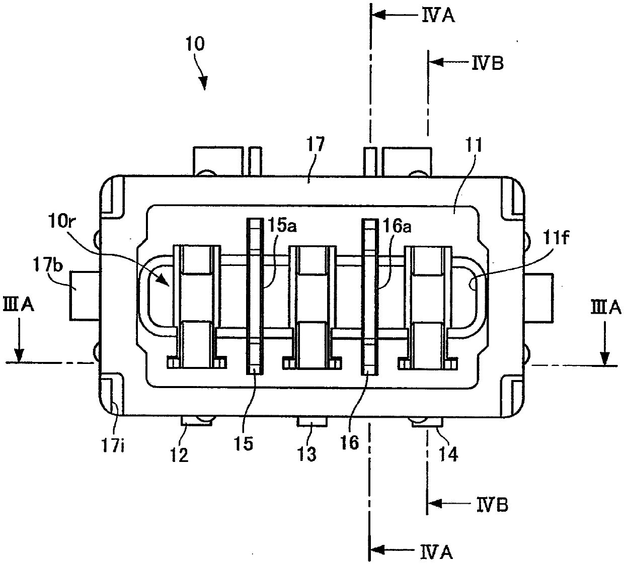
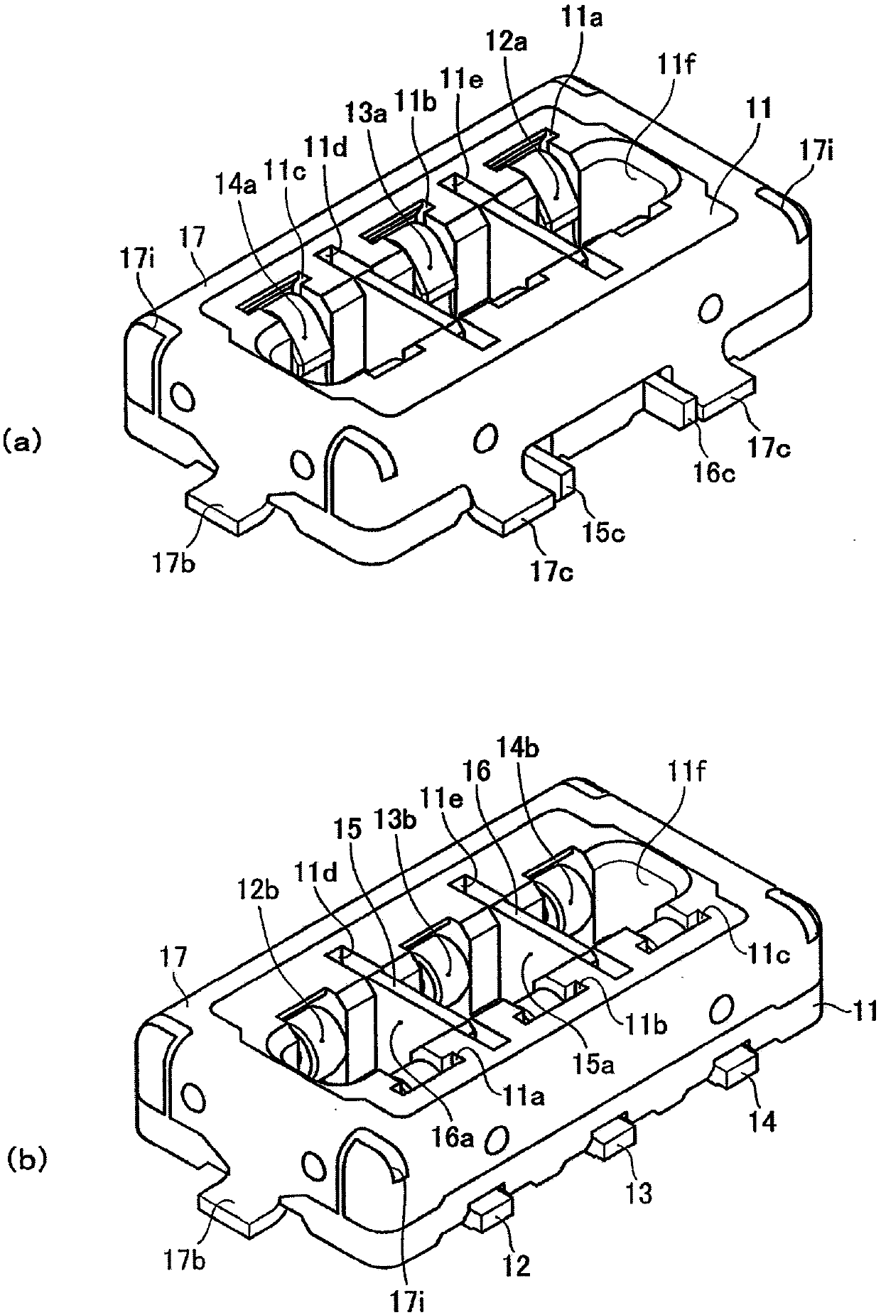
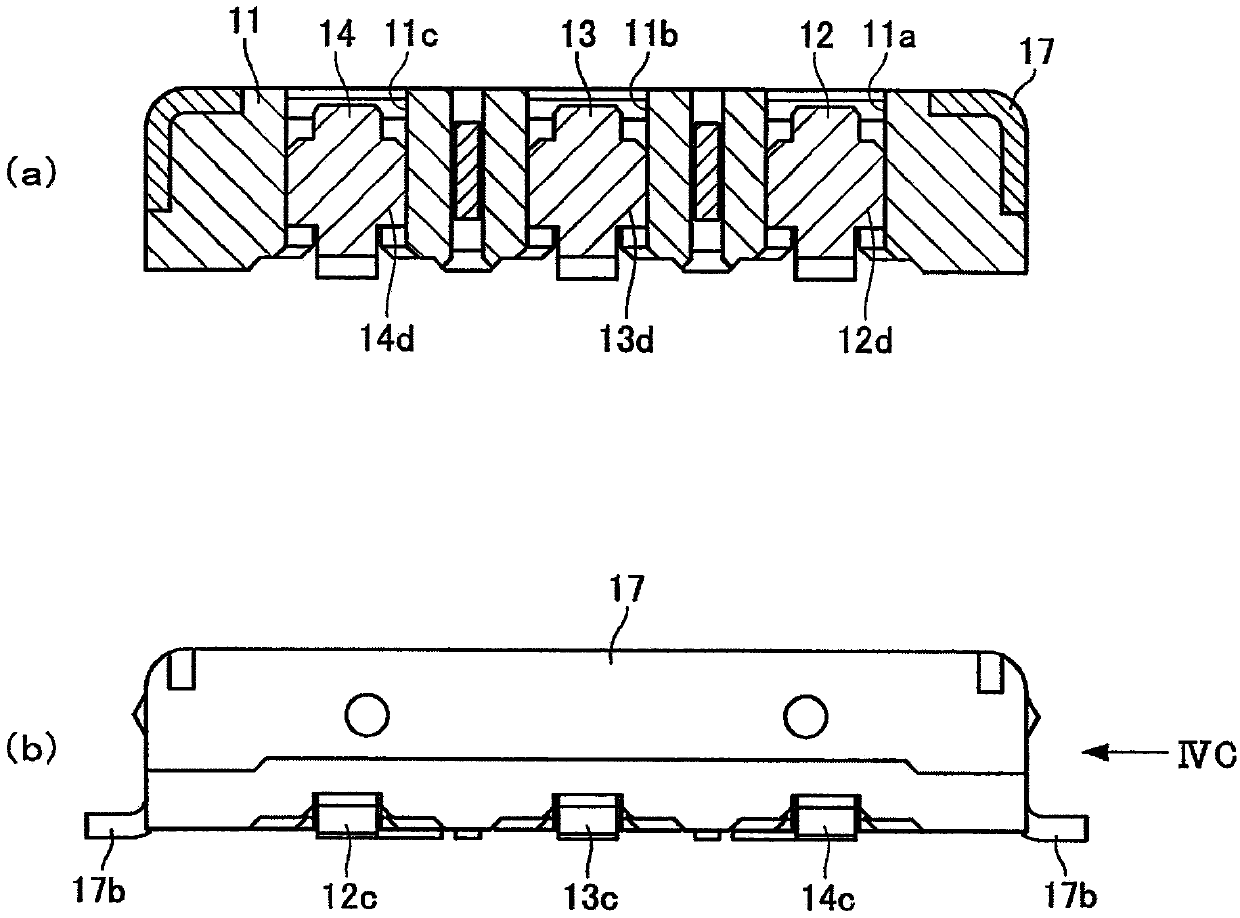
[0068] as figure 1 In general, the connector of this embodiment is configured as a receptacle 10 on the female side in a male-female connector set, and is connected to a plug 50 described later on the male side (refer to Figure 9 ) for concave-convex fitting and make the contact surfaces of the corresponding male and female signal terminals conduct conduction contact with each other with a specific contact pressure.

[0069] as Figure 1 to Figure 6 As shown in , generally, the socket 10, at the connector housing 11, the signal terminals 12, 13, 14 and the ground terminals 15, 16 (hereinafter, also referr...


PUM


Abstract

The invention provides a connector which can restrain the size of a product and enable impedance control to be easy, and provides a connector which can effectively restrain damages to a housing. The invention relates to the connector; in a connector housing (11), a plurality of terminals each provided with a contact surface with the corresponding object-side terminal are mutually separately mounted; the plurality of terminals (12-16) has ground terminals (15, 16) and a plurality of signal terminals (12, 13, 14) arranged side by side so as to be separated from each other in the direction of thecontact surface with the ground terminals (15, 16) interposed therebetween. The ground terminals (15, 16) are configured by conductor plates provided with plate surfaces (15a, 16a) that intersect with each other with respect to a direction in which the plurality of signal terminals (12, 13, 14) are separated from each other.

Description

technical field [0001] The present invention relates to connectors, and to connectors of quasi-coaxial configuration. Background technique [0002] Conventionally, for signal transmission such as high-frequency signals that require good signal transmission characteristics, a connector having a so-called pseudo-coaxial structure that is flat and improves transmission characteristics is used. [0003] As such a connector, it is known that a plurality of connection terminals (ground terminals and signal terminals) installed side by side are respectively provided at male and female connector housings, and by connecting the central ground terminal among the plurality of terminals It is connected to the ground potential and has a coplanar structure in which the signal terminals on both sides of the plurality of terminals are surrounded by the ground of the ground potential in the fitted state (for example, refer to Patent Document 1). [0004] In such a connector, there is an adv...

Claims


Application Information

Patent Timeline
Patent Type & Authority Applications(China)
IPC IPC(8): H01R13/6471H01R13/6473
CPCH01R13/6471H01R13/6473
Inventor 田中克佳浅井清大泽文雄
Owner SMK CO LTD
Learn More