
Discharge device for bone cement

A bone cement and operating device technology, applied in the direction of the surface coating liquid device, fixer, coating, etc., can solve the problem of the patient's danger in the barrel

Inactive Publication Date: 2013-07-24
HERAEUS MEDICAL
View PDF15 Cites 0 Cited by
  • Summary
  • Abstract
  • Description
  • Claims
  • Application Information

AI Technical Summary

Problems solved by technology

Flying barrels can be a hazard not only for patients but also for surgical staff

Method used


Image

  • Discharge device for bone cement
  • Discharge device for bone cement
  • Discharge device for bone cement

Examples


Embodiment Construction

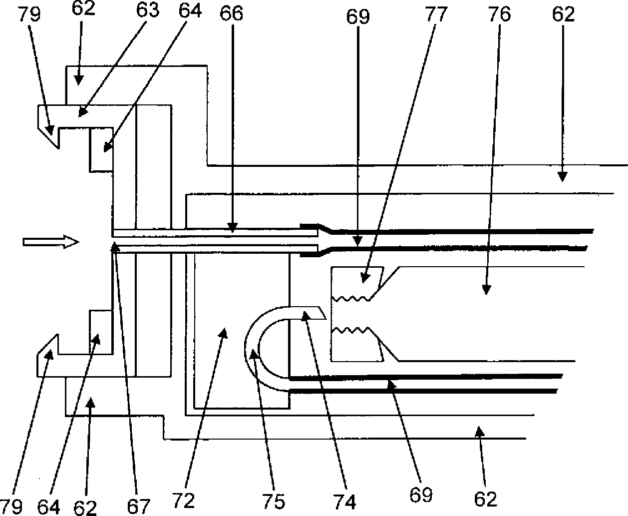
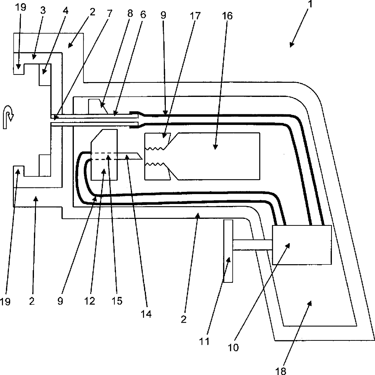
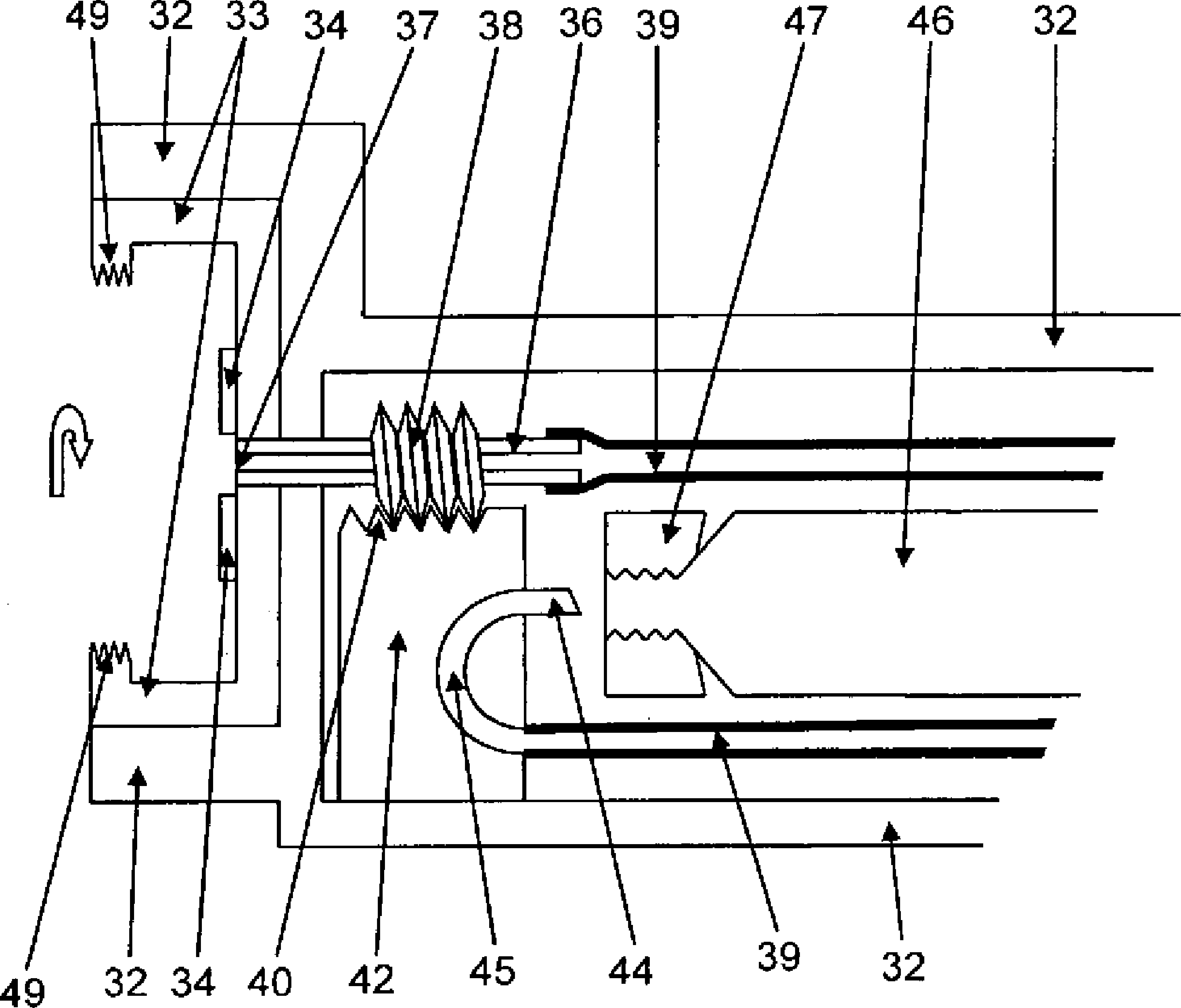
[0065] Figure 1 shows a schematic cross-sectional view of a dispensing device 1 according to the invention. The dosing device 1 comprises a housing 2 which can be made of plastic, for example. A carrier 3 with a seal 4 is arranged in the front of the housing 2 . The carrier 3 and thus the seal 4 are mounted rotatably in a sleeve formed by the housing 2 which accommodates the carrier 3 . The rotatability of the carrier 3 is indicated by hollow arrows. A cylindrical line 6 is connected to the support 3 and opens into an opening 7 in the support 3 . Via the opening 7 and the duct 6 the interior of the housing 2 is connected to the sleeve formed by the housing 2 or to the front side of the support 3 . A cam 8 is fastened to the pipe 6 , which rotates together with the rotation of the support 3 and thus the pipe 6 about the axis of the pipe 6 . This means that the support 3 is able to rotate about the axis formed by the duct 6 . The line 6 protrudes into the interior of the ho...


PUM


Abstract

The invention relates to a discharge device for discharging the content of a container by applying a compressed gas, comprising a housing, at least one compressed gas container, an operating device for setting a gas flow from the compressed gas container and an opening means for opening the compressed gas container, wherein the opening means is movable in relation to the compressed gas container, wherein the discharge device comprises a holder for securing the container on the discharge device and wherein the holder is in operative connection with the opening means in such a way that securing the container on the holder brings about a movement of the opening means in relation to the compressed gas container that opens the compressed gas container.

Description

technical field [0001] The invention relates to a dispensing device for pressing out the contents of a container by applying compressed gas, said dispensing device comprising a housing, at least one compressed gas tank, operating means for regulating the flow of gas from the compressed gas tank and An opening mechanism for opening the compressed gas tank, wherein the opening mechanism is movable relative to the compressed gas tank. [0002] The invention also relates to a method for activating the dispensing device and to the use of the ejection device according to the invention, in which method a container with material to be extruded is inserted into a holder of the dispensing device. [0003] The subject-matter of the invention is therefore also a compressed-gas-operated expulsion device for bone cement from a cartridge or another container. The compressed gas is provided here via a gas cartridge arranged in the discharge device. The ejector is a dispensing device in whic...

Claims


Application Information

Patent Timeline
Patent Type & Authority Applications(China)
IPC IPC(8): B05C17/015
CPCA61B17/8802B05C17/015B05C17/00596B05C17/00553B05C17/0052A61B17/8825A61B17/8822
Inventor S.福格特H.比希纳
Owner HERAEUS MEDICAL
Learn More