Multi-head precise three-dimensional numerical control planer-type milling machine

A gantry milling machine, precision technology, applied in the field of milling processing machinery, can solve the problems of increased moving resistance of the horizontal carriage, increased frictional resistance of the horizontal guide rail, and affecting the service life of the horizontal guide rail, so as to improve drive sensitivity, reduce power consumption, increase Effects of Stability and Machining Accuracy

Inactive Publication Date: 2013-07-31
JINAN RUIJIE MECHANICAL EQUIP
View PDF5 Cites 4 Cited by
  • Summary
  • Abstract
  • Description
  • Claims
  • Application Information

AI Technical Summary

Problems solved by technology

The deficiencies in the prior art are 1) the horizontal carriage is connected to the front vertical surface of the gantry through the horizontal guide rails, causing the tool rack connected to the horizontal carriage and the entire weight of the tool to be hooked on the vertical surface of the two horizontal guide rails It is in a suspended state, so that when the tool is working, it will tilt forward and shake, resulting in a decrease in the machining accuracy of the workpiece. The wear of the horizontal guide rail affects the service life and driving accuracy of the horizontal guide rail; 2) The tool holder is connected to the tool holder in a point-like manner through two vertical drag blocks. , it will swing back and forth with the vertical drag block as the axis, which will inevitably reduce the machining accuracy of the workpiece

Method used


Image

  • Multi-head precise three-dimensional numerical control planer-type milling machine
  • Multi-head precise three-dimensional numerical control planer-type milling machine
  • Multi-head precise three-dimensional numerical control planer-type milling machine

Examples


Embodiment Construction

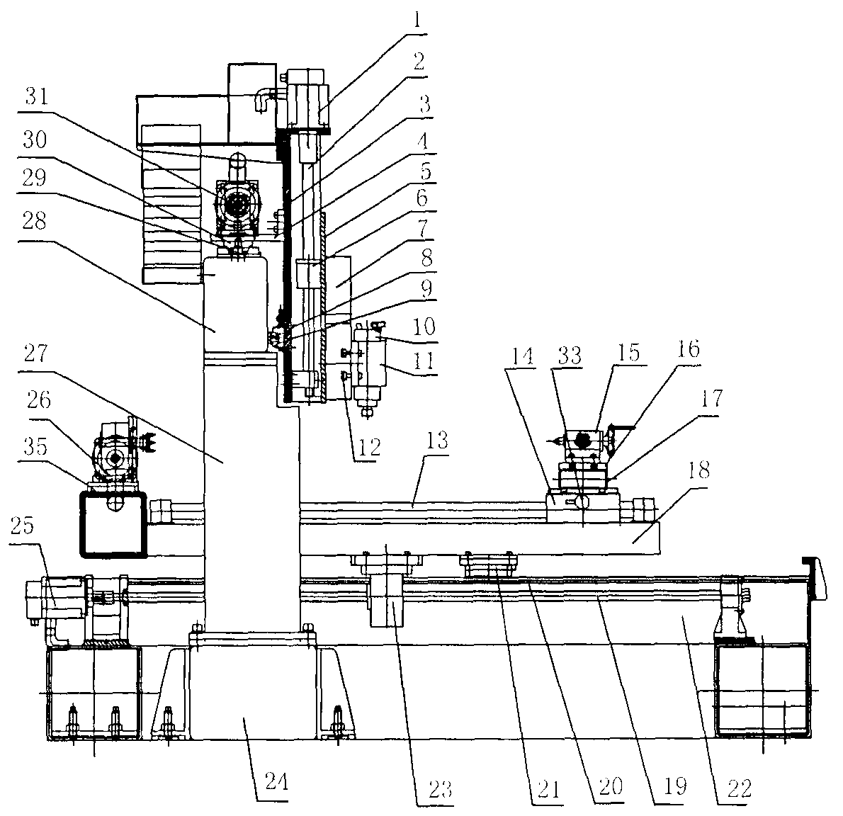
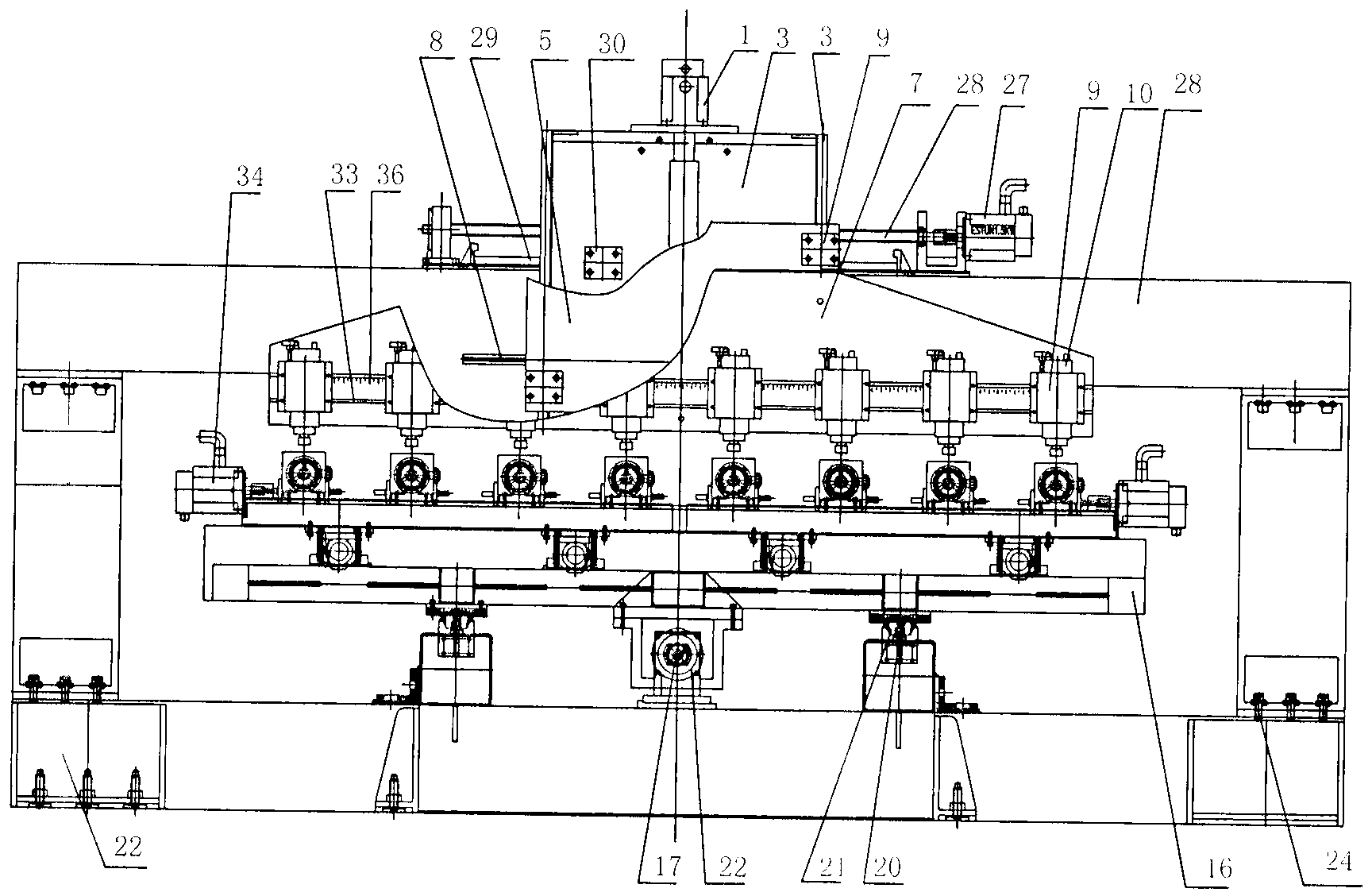
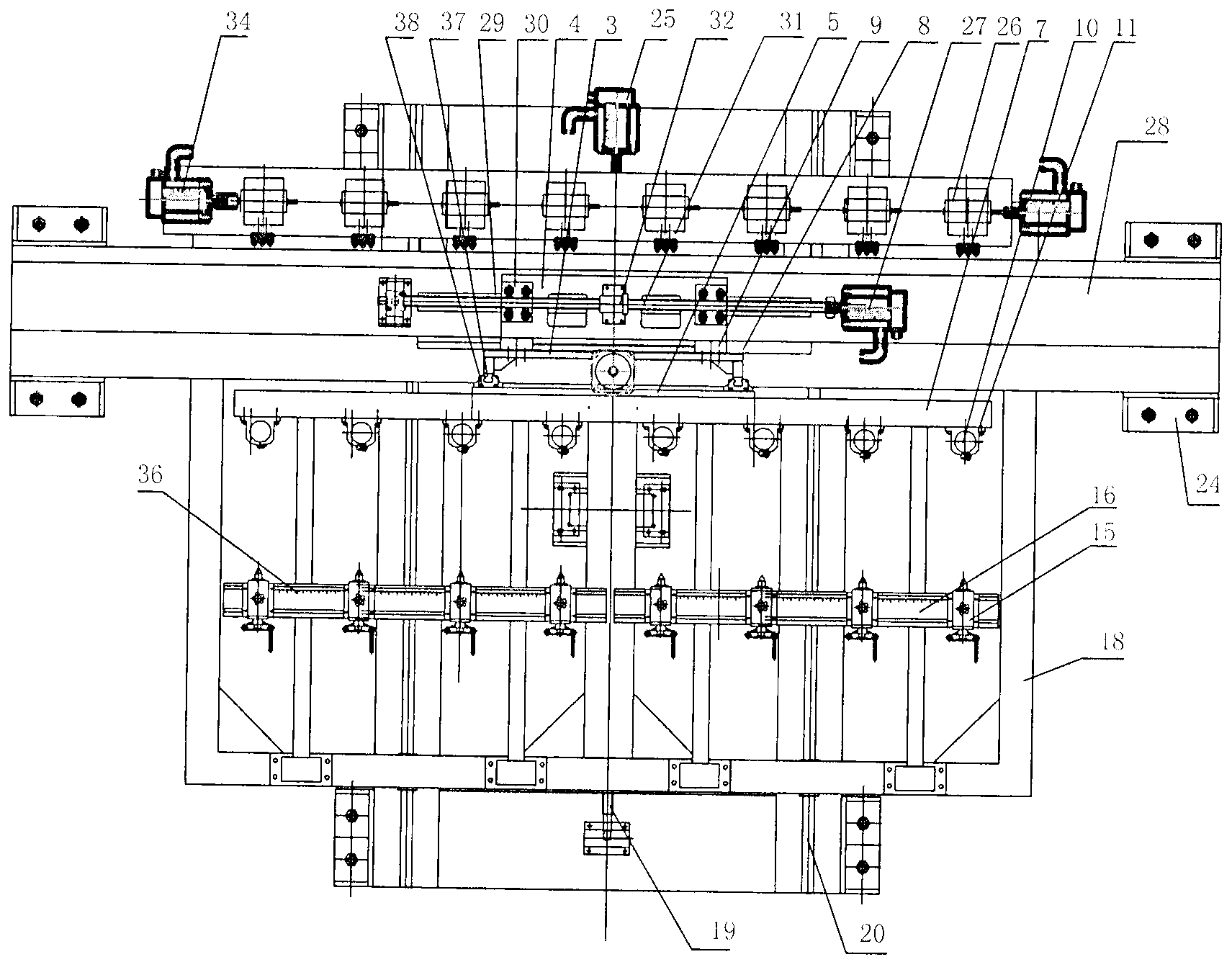
[0024] Numerical control milling machine of the present invention is described in further detail in conjunction with accompanying drawing:

[0025] The multi-head precision gantry engraving equipment of the present invention has a structure comprising: a horizontal Chinese-shaped machine base, a gantry frame 28, a longitudinally movable working platform 18, a workpiece positioning drive assembly, and a two-way precision drive composite machine head, wherein the horizontal Chinese-shaped machine base is It is made by vertically connecting the straight frame 22 and the square frame 24. The square frame 24 is set above the straight frame 22 through bolts, and the two ends of the straight frame 22 are connected with the gantry frame by the bolts 24. 28 lower ends are connected, and the top of the mouth-shaped support 24 is provided with a longitudinal slideway 20, and the middle of the longitudinal slideway 20 is provided with a longitudinal drive screw 19, and the end of the longi...


PUM


Abstract

The invention relates to a multi-head precise three-dimensional numerical control planer-type milling machine. The milling machine comprises a base with a shape of a horizontal Chinese character Zhong, a gantry, a vertically moving working platform, a workpiece positioning drive assembly, and a bidirectional precise drive composite head. The base is manufactured by vertically connecting a horizontal-I-shaped base and a square-frame-shaped base. The square-frame-shaped base is arranged above the horizontal-I-shaped base through bolts. The lower end of the horizontal-I-shaped base is connected with the gantry by bolts. Two vertical slide ways are arranged on the upper part of the square-frame-shaped base. A vertical driving screw is arranged between the vertical slide ways. A vertical screw driving motor is connected to an end of the vertical driving screw. Slide blocks are arranged on two sides on the bottom of the vertically moving working platform, and are slidably connected with the vertical slide ways on the upper part of the square-frame-shaped base. A nut is arranged at the middle on the bottom of the vertically moving working platform, and is connected with the middle of the vertical driving screw. The workpiece positioning drive assembly is arranged on the upper part of the vertically moving working platform.

Description

Technical field: [0001] The invention relates to a milling machine, in particular to a multi-head precision three-dimensional numerical control milling machine. Background technique: [0002] In the prior art, the head of the CNC milling machine moves in the direction established by the rectangular three-dimensional coordinate system. In the prior art, there is a servo motor driver in the base of the CNC milling machine, and the servo motor is connected to the gearbox on the machine base. There is a lifting carriage for loading tools, through which the three-dimensional movement of the workpiece and the tool can be realized. The horizontal movement of the CNC milling machine is realized by two horizontal guide rails arranged on the vertical surface of the front side of the gantry frame, that is, the horizontal dragging plate connected with the horizontal rails arranged horizontally and horizontally on the vertical surface of the front side of the gantry frame. There is a v...

Claims


Application Information

Patent Timeline
Patent Type & Authority Applications(China)
IPC IPC(8): B23C1/06B23Q1/01B23Q5/34B23Q5/28
Inventor 吴瑞明王如心
Owner JINAN RUIJIE MECHANICAL EQUIP
Why Eureka
Try Eureka