Injection-molding mould rotary-type-core de-molding mechanism

An injection mold and demolding mechanism technology, applied in the field of injection mold rotary core demolding mechanism, can solve problems such as reducing production efficiency, breaking plastic parts, affecting mold clamping and injection molding, etc.

Active Publication Date: 2013-07-31
YONGGAO CO LTD
View PDF9 Cites 20 Cited by
  • Summary
  • Abstract
  • Description
  • Claims
  • Application Information

AI Technical Summary

Problems solved by technology

[0002] When the injection mold is used to manufacture plastic parts, when the inner wall of the plastic part is made with internal threads, the existing technology is generally divided into two types. One is to use a stripping plate or a jack to force the plastic part off. The thread of the part is high, and when the thread groove corresponding to the core is deep, the plastic part will be broken by strong release, or the internal thread of the plastic part is broken in the thread groove of the core, which not only has

Method used


Image

  • Injection-molding mould rotary-type-core de-molding mechanism
  • Injection-molding mould rotary-type-core de-molding mechanism

Examples


Embodiment Construction

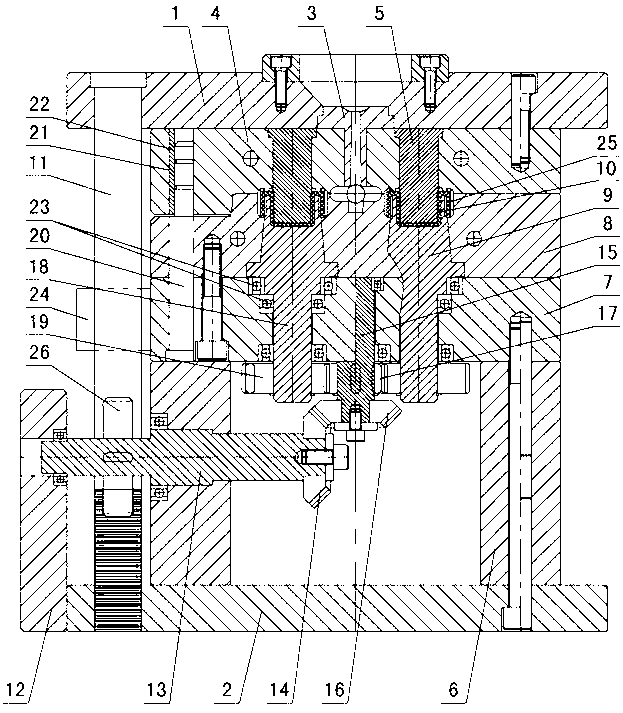
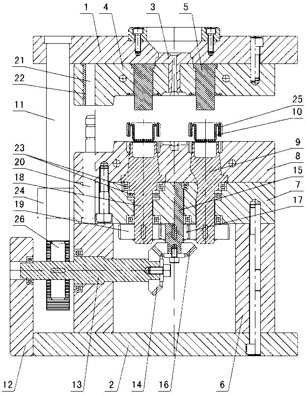
[0009] The invention relates to a rotary type core demoulding mechanism for an injection mold, such as figure 1 — figure 2 As shown, it includes the upper doubler plate 1 and the lower doubler plate 2, the sprue sleeve 3 is installed in the upper doubler plate, the fixed formwork 4 is installed under the upper doubler plate, the fixed mold core 5 is installed in the fixed formwork, and the lower doubler plate 2 Install the mold foot 6, install the bearing plate 7 on the mold foot, install the movable template 8 on the bearing plate, install the movable mold core 9 in the movable template, the movable mold core 9, the fixed mold core 5, the fixed template 4 and the movable template 8 There is an injection-molded plastic part 10 with thread in between, and the anti-rotation rib 25 is formed on the plastic part, and it is characterized in that: a spur rack 11 is installed under the upper doubler plate 1, and a baffle plate 12 is installed on one side of the lower doubler plate 2...


PUM


Abstract

The invention relates to an injection-molding mould rotary-type-core de-molding mechanism comprising upper and lower doubling plates. A sprue bush is arranged in the upper doubling plate. A fixed mold plate is arranged below the upper doubling plate. A fixed mold core is arranged in the fixed mold. Mold feet are arranged on the lower doubling plate. A bearing plate is arranged on the mold feet. A moving mold plate is arranged on the bearing plate. A moving mold core is arranged in the moving mold. Injection-molded threaded plastic parts are arranged among the moving mold core, the fixed mold core, the fixed mold plate, and the moving mold plate. Rotation-stopping ribs are provided on the plastic parts. The mechanism is characterized in that a straight rack is arranged below the upper doubling plate. A baffle is arranged on one side of the lower doubling plate. A gear shaft is arranged in the baffle and mold feet. A transmission gear and a large bevel gear are arranged on the gear shaft. The straight rack is engaged with the transmission gear. A driving shaft is arranged in the bearing plate. A small bevel gear and a driving gear are arranged on the driving shaft. The small bevel gear is engaged with the large bevel gear. A driven shaft is arranged below the moving mold core. A driven gear is arranged on the driven shaft. The driven gear is engaged with the driving gear.

Description

technical field [0001] The invention relates to an injection mold, in particular to a rotary type core ejection mechanism of the injection mold. Background technique [0002] When the injection mold is used to manufacture plastic parts, when the inner wall of the plastic part is made with internal threads, the existing technology is generally divided into two types. One is to use a stripping plate or a jack to force the plastic part off. The thread of the part is high, and when the thread groove corresponding to the core is deep, the plastic part will be broken by strong release, or the internal thread of the plastic part is broken in the thread groove of the core, which not only has a high scrap rate of plastic parts, but also affects The next time the mold is closed for injection molding; the second is to drive the movable mold core to rotate through the motor to make the plastic parts come out. The disadvantage of this structure is that the motor needs to be started after...

Claims


Application Information

Patent Timeline
IPC IPC(8): B29C45/40
Inventor 张建均王秋雷陈志伟
Owner YONGGAO CO LTD
Why Eureka
Try Eureka