Hydraulic engineering driller

An engineering drilling rig, hydraulic technology, applied in the direction of rotary drilling rig, percussion drilling, rotary drilling, etc., can solve problems such as difficulty in tower installation, inconvenient movement and transfer, and difficulty in aligning hole positions, so as to achieve saving The effect of using cost and labor cost, optimizing equipment layout space, and simple and light equipment structure

Inactive Publication Date: 2013-07-31
CHONGQING HAIBEN HYDRAULIC MACHINERY MFG
View PDF5 Cites 11 Cited by
  • Summary
  • Abstract
  • Description
  • Claims
  • Application Information

AI Technical Summary

Problems solved by technology

[0004] The engineering drilling rig of the above-mentioned structure mainly has the following deficiencies: 1. The power head of the motor-driven transmission or reducer has a small speed range or only a rated speed, so the power torque does not change much, and it is difficult to drill into complex formations. Poor stability of pile construction
2. The transmission, reducer, commutator and other assemblies are not equipped with safety overload protection devices
When drilling into complex formations, it is easy to cause damage to parts, especially to the bevel gear
3. The brake wheels at the left and right ends of the hoist are equipped with lifting brakes and braking brakes. There is no self-locking device between the two brakes. When the lifting brakes and braking brakes are tightened at the same time, mechanical accidents or parts may be caused. be damaged
4. The main drill pipe is clamped by the power head chuck, and the power head is moved by the column or the gantry oil cylinder. Since the hydraulic cylinder directly acts on the drill pipe, the equipment layout space is limited, resulting in the usual moving stroke of the drill pipe being about 0.5-1 meter , so the drilling distance is short, which directly affects the one-time loading and unloading construction of cast-in-situ piles, and at the same time increases the number of drilling movements and reduces the efficiency of drilling construction
5. The flange butt joint drill pipe is connected by bo

Method used


Image

  • Hydraulic engineering driller
  • Hydraulic engineering driller
  • Hydraulic engineering driller

Examples


Example Embodiment

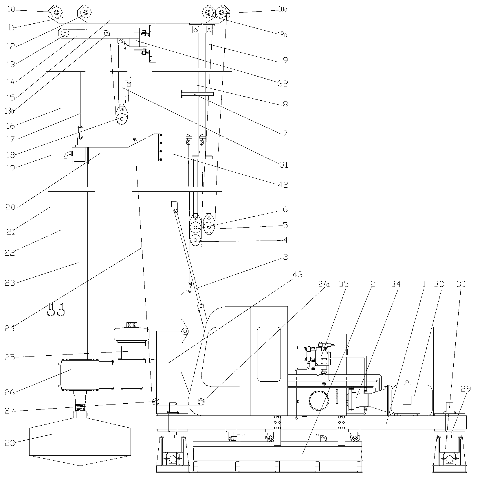
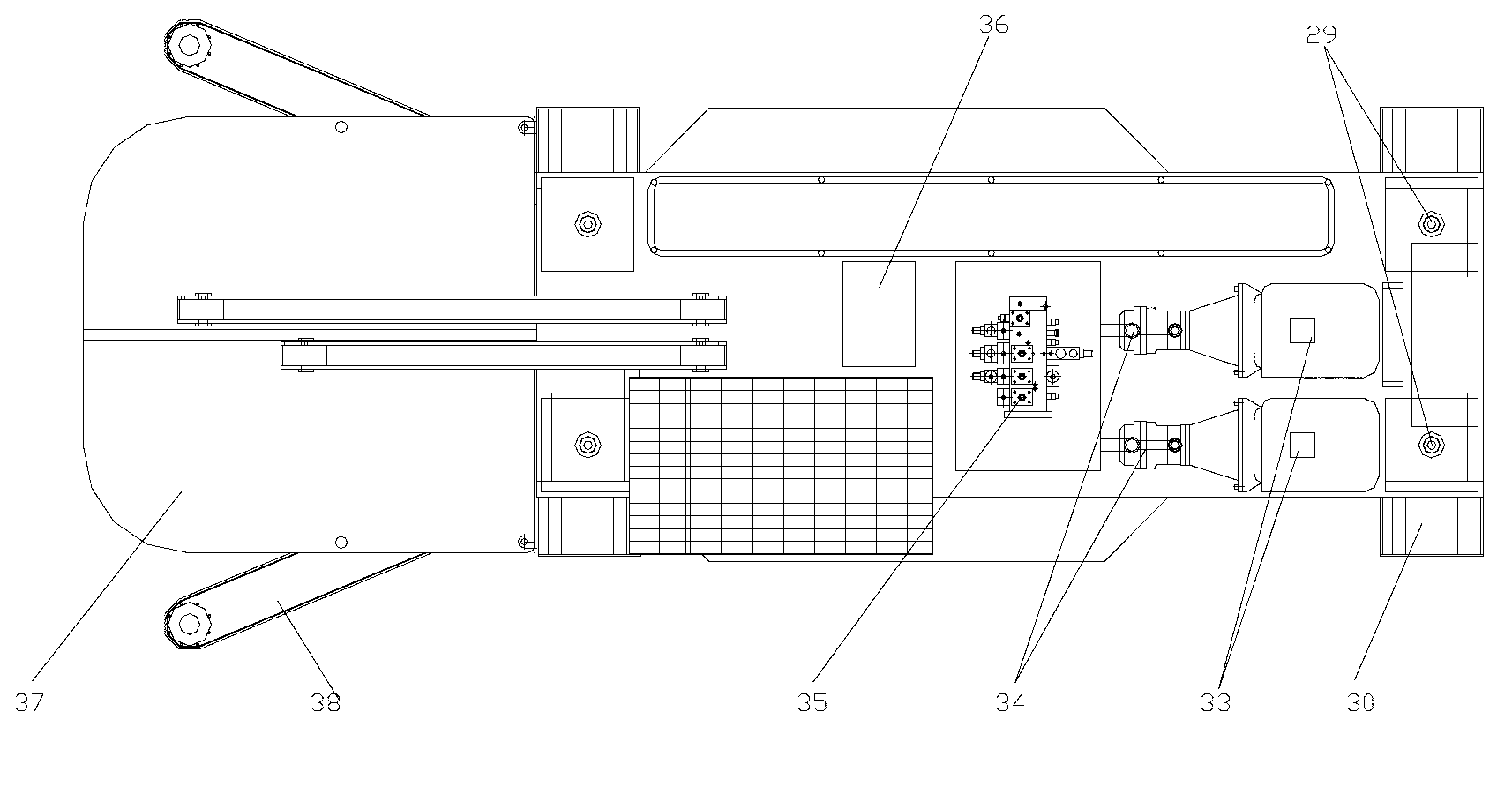
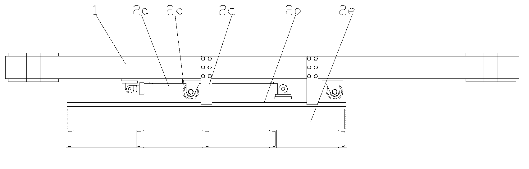
[0034] figure 1 Is a schematic diagram of the structure of the present invention, figure 2 for figure 1 Top view of image 3 Schematic diagram of longitudinal walking mechanism, Figure 4 Is the longitudinal cross-sectional view of the horizontal traveling mechanism, Figure 5 Is a schematic diagram of the structure of the lateral walking mechanism, Image 6 It is a schematic diagram of the structure of the drill bit assembly, as shown in the figure: the hydraulic engineering drill of this embodiment includes a base 1, a column 42, a drilling assembly, a hydraulic drive system, and a power system;

[0035] The drilling assembly includes a drill bit assembly, a power head 26 and a guide tailstock 20. The drill bit assembly includes a drill bit 28 and a drill rod assembly 23. The end of the drill rod assembly 23 is set on the guide tailstock in a single degree of freedom in a circumferentially rotatable manner. 20. The structure can adopt the existing rotary joint structure, that i...


PUM


Abstract

The invention discloses a hydraulic engineering driller which adopts a drilling hydraulic cylinder and a hydraulic motor driven drilling bit component for drilling; a drilling stroke is controlled by the drilling hydraulic cylinder through a pulley block; the drilling hydraulic cylinder is laid out relatively flexibly; the equipment layout space is optimized; the drilling component has a greater ascent and descent space fundamentally; the drilling stroke is prolonged; the drilling movement frequency is reduced, so that the drilling construction efficiency is improved; in addition, due to the optimization, the equipment layout space can be made full use of, so that the driller is compact in structure; with the adoption of a hydraulic driving structure and electrohydraulic control, a stepless speed regulation function is realized, and the driller can meet the drilling requirements of different stratums; a power head is driven by a hydraulic motor and can be combined with mechanical speed reduction, the power transmission reliability is improved further, and the adjustable scope of torque variation is wider; and when the equipment is in use, the labor intensity is reduced, the use cost and labor cost are saved, and the driller can be used for engineering pile hole construction and meets the technological requirements.

Description

Technical field [0001] The invention relates to an engineering machine, in particular to a hydraulic engineering drilling rig. Background technique [0002] Engineering drilling rigs are used for large-diameter cast-in-place pile construction in electric power construction, bridges, high-rise buildings, dams, ports and wharfs. [0003] In the prior art, the traditional mechanical circulation drilling rig uses a motor or an internal combustion engine as a power source, drives a transmission or a reducer, and then switches the transmission shaft through a commutator to realize the power of the power head of the drilling rig or the power of the coiling field respectively. One type of circulating drilling rig power head transmission and hoisting and hoisting transmission are each equipped with a transmission system. The chuck of the power head is arranged above or below the main shaft of the power head, and the main drill rod is installed in the square hole or hexagonal hole of the ch...

Claims


Application Information

Patent Timeline
IPC IPC(8): E21B7/02E21B3/02
Inventor 尹书勤尹渝
Owner CHONGQING HAIBEN HYDRAULIC MACHINERY MFG
Why Eureka
Try Eureka