
Fiber Bragg Grating Displacement Meter

A fiber grating, displacement meter technology, applied in the direction of using optical devices, measuring devices, instruments, etc., can solve problems such as the accuracy of roof measurement and the need for real-time measurement, and achieve the effect of wide application range and guaranteed accuracy.

Inactive Publication Date: 2016-12-07
XIAN UNIV OF SCI & TECH
View PDF7 Cites 0 Cited by
  • Summary
  • Abstract
  • Description
  • Claims
  • Application Information

AI Technical Summary

Problems solved by technology

[0002] Displacement measurement is a technical problem often encountered in the engineering field. Common measuring instruments cannot solve the need for accurate and real-time measurement of the roof in the roadway

Method used


Image

  • Fiber Bragg Grating Displacement Meter
  • Fiber Bragg Grating Displacement Meter
  • Fiber Bragg Grating Displacement Meter

Examples


Embodiment Construction

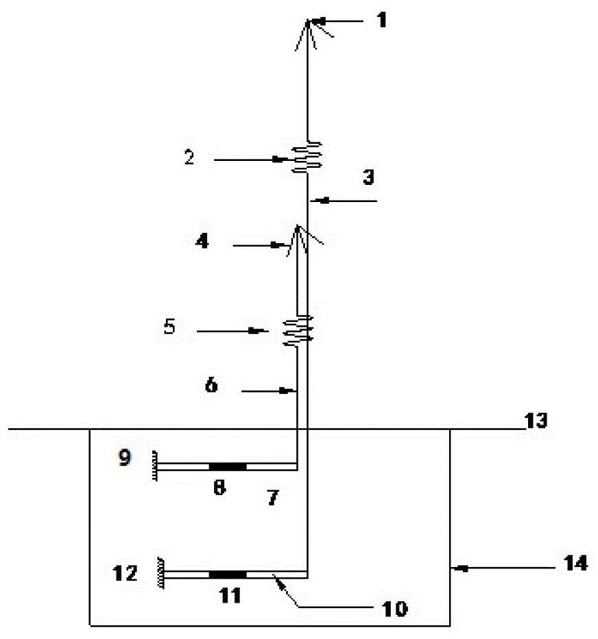
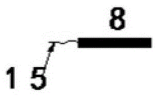
[0034] This optical fiber grating top plate displacement gauge comprises anchor fluke 1,2, steel wire rope 3,6, spring 2,5, sensor 8,11, cantilever beam 7,10 and housing 14, and above-mentioned housing 14 is fixed on the bottom surface of top plate 13, and top plate 13 is a rock mass, and there is a hole on the top plate 13, the hole goes deep into the rock mass, the anchor claw is fixed at the base point of the hole, and the anchor claw is connected to the cantilever beam through the springs 2, 5 and the wire rope 7, 10 free ends, the other end of the cantilever beams 7, 10 relative to the free ends is a fixed end, the fixed ends are fixed on the housing 14, and the sensors 8, 11 are pasted on the cantilever beams 7, 10. There are two holes, the deeper hole has a deep base point, the shallower hole has a shallow base point, and the anchor flukes 1, 2 and the cantilever beams 7, 10 also have two correspondingly, one The anchor fluke 1 is fixed at the deep base point, the other...


PUM


Abstract

The invention discloses a fiber grating displacement meter. The displacement meter comprises anchor flukes, connecting pieces, elastic pieces, sensors, cantilever beams and a casing, wherein the casing is fixed to the bottom surface of a top plate; holes are formed in the top plate and go deep into a rock mass; the anchor flukes are fixed to the base points of the holes and are connected with the free ends of the cantilever beams through the connecting pieces and the elastic pieces; the other ends, which are opposite to the free ends, of the cantilever beams are fixed ends; the fixed ends are fixed on the casing; and the sensors are stuck to the cantilever beams. The displacement meter provided by the invention has a wide application range, can be applied to top plate sinkage monitoring for various tunnel projects and subway projects and can ensure measuring accuracy.

Description

technical field [0001] The invention relates to a displacement measuring device, in particular to a fiber grating top plate separation displacement meter. Background technique [0002] Displacement measurement is a technical problem often encountered in the engineering field. Common measuring instruments cannot meet the needs of accurate and real-time measurement of the roof in the roadway. Contents of the invention [0003] The invention provides a fiber grating displacement meter, in particular a fiber grating top plate displacement meter, which can accurately and real-time measure the displacement of the top plate. [0004] The optical fiber grating top plate displacement meter includes anchor flukes 1, 2, connecting parts, elastic parts 2, 5, sensors 8, 11, cantilever beams 7, 10 and a housing 14. Above-mentioned casing 14 is fixed on the bottom surface of top plate 13, and top plate 13 is a rock mass, and there is a hole on the top plate 13, and this hole goes deep i...

Claims


Application Information

Patent Timeline
Patent Type & Authority Patents(China)
IPC IPC(8): G01B11/02
Inventor 肖江丁威周虎陈超梁军陆阳
Owner XIAN UNIV OF SCI & TECH
Learn More