Leg crossing device

A technology of a fork-leg device and a fan gear, which is applied to gymnastics equipment, sports accessories, etc., can solve the problems of insufficient synchronization and inconvenience when the two legs are spread out.

Inactive Publication Date: 2013-08-07
NANYANG INST OF TECH +1
View PDF5 Cites 1 Cited by
  • Summary
  • Abstract
  • Description
  • Claims
  • Application Information

AI Technical Summary

Problems solved by technology

[0002] In fitness exercises, there are many people who stretch their lower limbs through splits, but because there are no special equipment and facilities, they usually exercise on the ground, which is very inconvenient
Although some have simple settings, the spread of the legs is not synchronized enough

Method used


Image

  • Leg crossing device
  • Leg crossing device

Examples


Embodiment Construction

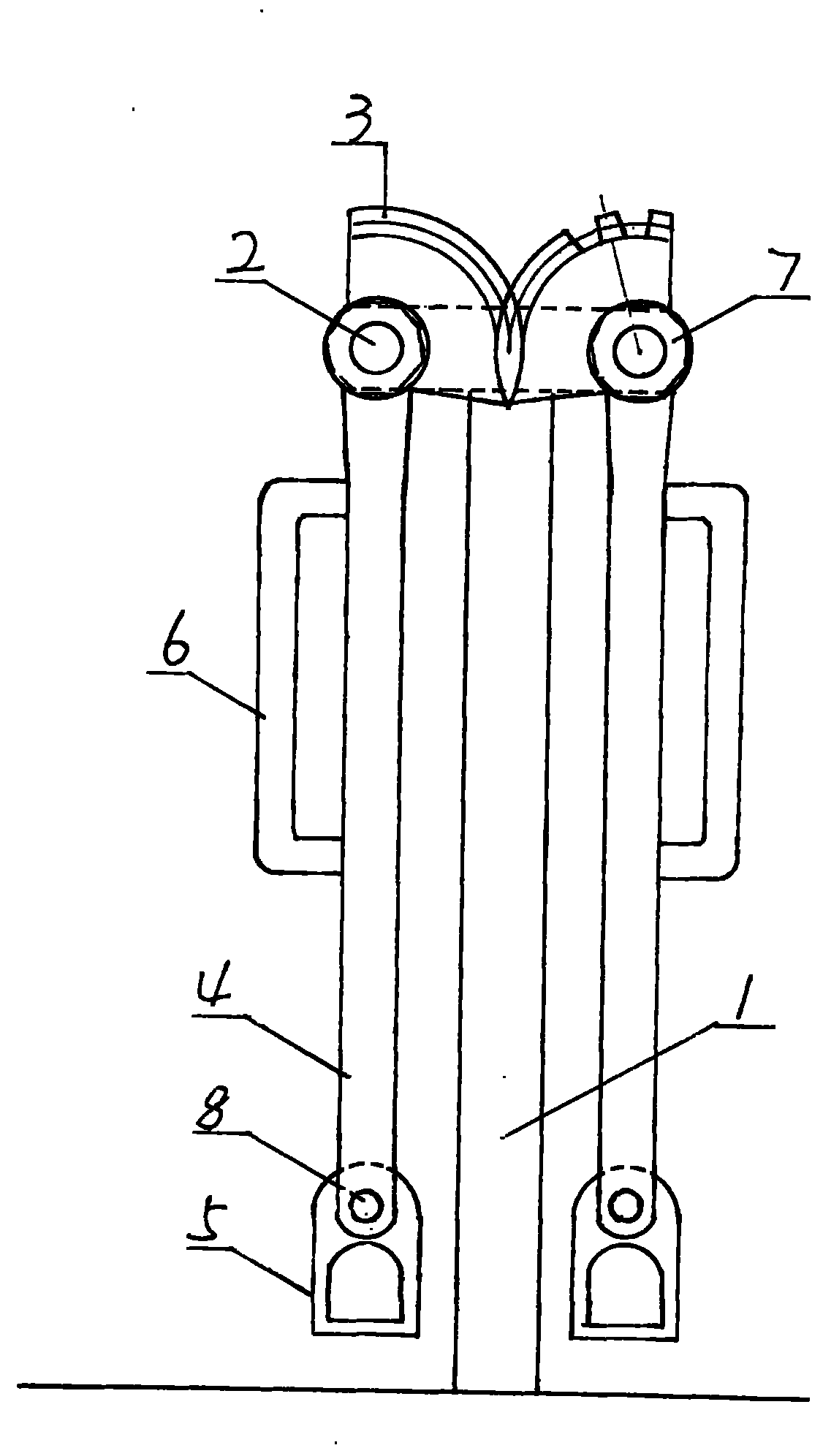
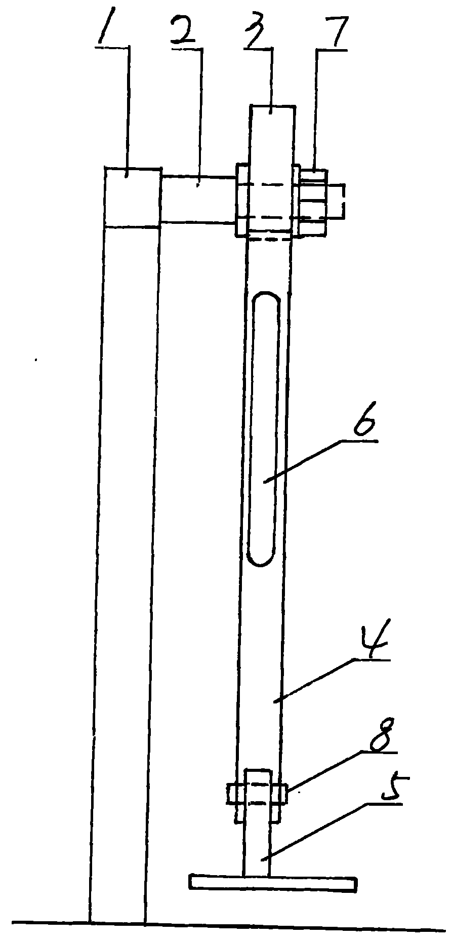
[0007] Such as figure 1 , 2 As shown, a leg crossing device is used to meet people's fitness needs. The structure is composed of bracket 1, shaft head 2, sector gear 3, vertical beam 4, pedal 5 and handrail 6. The support 1 is a T-shaped frame, and the bottom end of the support 1 is vertically fixedly connected with the ground to form a whole. One side of the upper end of the support 1 is symmetrically provided with a shaft head 2, the longitudinal section of the shaft head 2 is convex, and one end of the shaft head 2 is provided with a thread, and the shaft head 2 and the support 1 are vertically connected into one. A sector gear 3 (that is, a part of the gear) is installed on the shaft head 2, and the two sector gears 3 are meshed. A nut 7 is installed on the thread of the shaft head 2, and the nut 7 fixes the sector gear 3 on the shaft head 2. The sector gear 3 can flexibly rotate on the shaft head 2. A vertical beam 4 is connected to the sector gear 3 below the shaft h...


PUM


Abstract

A leg crossing device structurally comprises a support, shaft heads, sector gears, vertical beams, pedals and armrests. The support is vertically and integrally connected with the ground, the shaft heads are arranged at the upper end of the support, the two sector gears are mounted on the shaft heads and engaged with each other, the vertical beams are connected on the sector gears, the pedals are connected at the lower ends of the vertical beams and can swing back and forth at one end of the corresponding vertical beam, and one armrest is arranged on one side of the corresponding vertical beam and is fixedly and integrally connected with the vertical beam.

Description

technical field [0001] A leg crossing device belongs to the field of fitness equipment. Background technique [0002] In fitness exercises, there are many people who open their lower limbs through splits, but because there are no special equipment and facilities, they usually exercise on the ground, which is very inconvenient. Although some have simple settings, the spread of the legs is not synchronous enough. Contents of the invention [0003] The purpose of the present invention is to provide a leg crossing device to meet people's fitness needs. The structure is composed of brackets, shaft heads, sector gears, vertical beams, pedals and handrails. The support is a T-shaped frame, and the bottom end of the support is vertically fixedly connected with the ground and integrated into one. A shaft head is symmetrically arranged on one side of the upper end of the support, the longitudinal section of the shaft head is convex, and one end of the shaft head is provided with ...

Claims


Application Information

Patent Timeline
Patent Type & Authority Applications(China)
IPC IPC(8): A63B23/04
Inventor 冯政
Owner NANYANG INST OF TECH
Why Eureka
Try Eureka