
Novel transverse elasticity positioning method of side-rolling resistant torsion bar for railway vehicle and device of method

An anti-roll torsion bar and elastic positioning technology, which is applied to bogies, transportation and packaging, railway car body parts, etc., can solve the problem that the anti-roll torsion bar system cannot effectively perform lateral positioning

Active Publication Date: 2013-08-14
ZHUZHOU TIMES NEW MATERIALS TECH
View PDF5 Cites 11 Cited by
  • Summary
  • Abstract
  • Description
  • Claims
  • Application Information

AI Technical Summary

Problems solved by technology

[0008] The purpose of the present invention is to provide a new lateral elastic positioning method for the anti-roll torsion bar for rail vehicles in view of the requirement that the anti-roll torsion bar system of the existing general structure cannot effectively perform lateral positioning

Method used

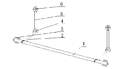

Image

  • Novel transverse elasticity positioning method of side-rolling resistant torsion bar for railway vehicle and device of method
  • Novel transverse elasticity positioning method of side-rolling resistant torsion bar for railway vehicle and device of method
  • Novel transverse elasticity positioning method of side-rolling resistant torsion bar for railway vehicle and device of method

Examples


specific Embodiment approach

[0031] In order to explain the technical solutions of the embodiments of the present invention more clearly, the following will briefly introduce the drawings used in the description of the embodiments. Obviously, the drawings in the following description are only some embodiments of the present invention. A person of ordinary skill in the art can obtain other drawings based on these drawings without creative work.

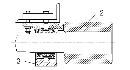
[0032] As attached Figure 7 As shown in the first embodiment, the present invention provides a new type of lateral elastic positioning method for anti-rolling torsion rods for rail vehicles. Firstly, a groove is opened at the opposite assembly end of the supporting seat 3 and the torsion arm 2; An elastic thrust pad 12 is provided between the torsion arm 2 and the elastic thrust pad 12 is a two-half structure, which facilitates the assembly and use of the elastic thrust pad 12, including the left end cover 7, the right end cover 10, the rubber 8 and the partition 9; ...


PUM


Abstract

The invention provides a novel transverse elasticity positioning method of a side-rolling resistant torsion bar for a railway vehicle. A groove is formed at each of assembling ends of a supporting seat and a torsion arm; an elastic thrust pad is arranged between the supporting seat and the torsion arm for transverse elasticity positioning; and the two ends of the elastic thrust pad are fixed on the supporting seat and the torsion arm by bolts or pins respectively for achieving circumferential positioning, and ensuring no circumferential movement during torsion or shearing. The method achieves no transverse impact or transverse motion in a using process of the side-rolling resistant torsion bar for the railway vehicle, and the elastic thrust pad and a torsion bar component are subjected to torsional deformation simultaneously, and bear a vertical load and an impact load, so that a side-rolling resistant function, a shock absorption function and a noise reduction function of the side-rolling resistant torsion bar for the railway vehicle are ensured.

Description

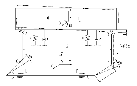
technical field [0001] The invention relates to a vehicle positioning method and a positioning device, in particular to a lateral positioning method of an anti-rolling torsion bar of a rail vehicle and a device for realizing lateral positioning. Background technique [0002] The vibration of the vehicle mainly has degrees of freedom in six directions: stretching vibration in the X direction, yaw vibration in the Y direction, ups and downs vibration in the Z direction, nodding vibration around the Y axis, shaking head vibration around the Z axis, and sideways vibration around the X axis. Roll vibration. The current bogies of rail transit vehicles are all two-stage suspensions, and the anti-roll torsion bar system plays a role in adjusting the roll stiffness of the vehicle and controlling the roll vibration of the vehicle. [0003] The mechanism motion diagram of the anti-roll torsion bar system is as follows: figure 1 As shown, M in the figure is the car body, E and F are c...

Claims


Application Information

Patent Timeline
IPC IPC(8): B61F5/50
Inventor 罗斌刘文松杜方孟吕士勇程海涛高发雄
Owner ZHUZHOU TIMES NEW MATERIALS TECH
Learn More