Supercharge Your Innovation With Domain-Expert AI Agents!

Composite accumulator

A technology of accumulators and pressure sensors, applied to accumulator devices, pressure vessels, and methods for container discharge

Active Publication Date: 2013-08-14
GM GLOBAL TECH OPERATIONS LLC
View PDF5 Cites 5 Cited by
  • Summary
  • Abstract
  • Description
  • Claims
  • Application Information

AI Technical Summary

Problems solved by technology

Although the design of these accumulators is suitable for their intended purpose, there is still room for improvement in the art for accumulators such that the accumulators comprise composite materials without degrading the performance characteristics of the accumulators

Method used


Image

  • Composite accumulator

Examples


Embodiment Construction

[0061] The following description is merely exemplary in nature and is not intended to limit the invention, the application or uses of the invention.

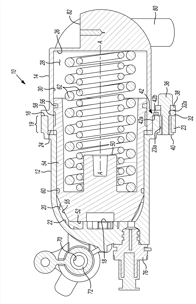
[0062] Referring to the drawings, reference numeral 10 generally indicates an accumulator in accordance with the principles of the invention. The accumulator 10 is an energy storage device within which incompressible hydraulic fluid is maintained under pressure by an external source. In the example provided, the accumulator 10 is a spring-type accumulator that provides a compressive force on hydraulic fluid within the accumulator 10, as will be described in more detail below. The accumulator 10 is preferably used in a hydraulic control system of an automatic transmission (not shown) to enable stop-start operation or hybrid hydraulic operation. It should be appreciated, however, that the accumulator 10 may also be used in various other environments without departing from the scope of the present invention, such as in fuel inject...


PUM


Abstract

A composite accumulator includes a base having a closed end and an open end, the base having an inner surface that defines a cavity and having a fluid port in communication with the cavity for communicating a hydraulic fluid in and out of the cavity. A cover is disposed over the open end of the base and is secured to the base by a fastener. A piston is disposed within the base and the cover. The piston is sealed to the inner surface of the cover and is translatable along an axis. A biasing member is disposed within the base and the cover and located axially between the piston and the cover. The base and the cover are plastic.

Description

technical field [0001] The present invention relates to composite accumulators. More specifically, the present invention relates to compound spring-loaded accumulators configured for use in automotive powertrains. Background technique [0002] The statements in this section merely provide background information related to the present invention and may or may not constitute prior art. [0003] A typical automatic transmission includes a hydraulic control system used to provide lubrication, cooling, and control the various components of the transmission. The pump circulates hydraulic fluid under pressure throughout the transmission. The pump is usually driven by the engine of the motor vehicle. In stop and start situations, it is desirable to shut down the engine in order to maximize fuel efficiency. But shutting down the engine in turn shuts down the pump. To pre-arm control devices within a transmission, such as clutches and brakes, accumulators may be employed in hydra...

Claims


Application Information

Patent Timeline
Patent Type & Authority Applications(China)
IPC IPC(8): F15B1/04
CPCF17C7/00F15B1/045F15B1/04
Inventor E.W.梅勒C.E.梅林C.K.比勒J.B.博尔格森L.贝辛P.C.隆德贝里G.E.克勒弗G.H.佩利克
Owner GM GLOBAL TECH OPERATIONS LLC
Features
  • R&D
  • Intellectual Property
  • Life Sciences
  • Materials
  • Tech Scout
  • Unparalleled Data Quality
  • Higher Quality Content
  • 60% Fewer Hallucinations
Learn More